
What is TWI? TWI stands for Two Wire Interface. We previously learn about segment display (SSD). SSD require many GPIO pin that could be used for any other purpose. We can use only 2 wires for up to 6SSD display at a same time. So only 2GPIO pins can be used for controlling up to 6 seven segment display. In that case we use a special IC TM1637. It will come with a compact package. TM1637 is a kind of LED(light emitting diode display) drive control special circuit with keyboard scan interface and it’s internally integrated with MCU digital interface, data latch, LED high pressure drive and keyboard scan
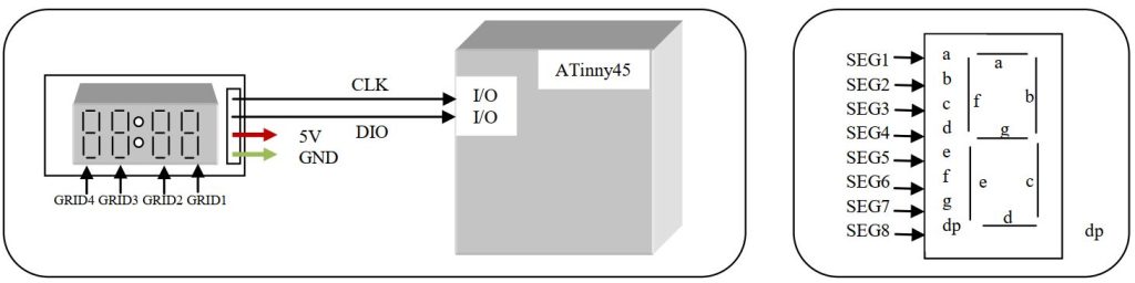
Here the SSD are common anode type display. Let’s look the datasheet how to interface.
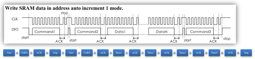
Let’s begin with start, stop and acknowledge function. First we make a function for some delay. Here we will not stop the processor by using _delay_ms or _delay_us function. We passing a loop without operation.
void _cpu_delay(uint32_t i)
{
    while (i > 0) {
    	for (uint32_t j = 0; j < 10; j++) {
    		asm("nop");
    	}
    	i--;
    }
}
For start condition first set both CLK and DIO pin high then set low the DIO pin. Program for the start condition
void tm1637_Start(void)
{
	TM1637_CLK_PORT|=(1<<TM1637_CLK_PIN); //CLK pin low
	TM1637_DIO_PORT|=(1<<TM1637_DIO_PIN); //DIO pin high
	_cpu_delay(5);
	TM1637_DIO_PORT&=~(1<<TM1637_DIO_PIN); //DIO pin low
}
For stop condition both the CLK and DIO pin set low. After a delay first set CLK pin to high again some delay set the DIO pin to high.
void tm1637_Stop(void)
{
	TM1637_CLK_PORT&=~(1<<TM1637_CLK_PIN); //CLK pin low
	//_cpu_delay(5);
	TM1637_DIO_PORT&=~(1<<TM1637_DIO_PIN); //DIO pin low
    _cpu_delay(5);
    TM1637_CLK_PORT|=(1<<TM1637_CLK_PIN);  //CLK pin high
    _cpu_delay(5);
    TM1637_DIO_PORT|=(1<<TM1637_DIO_PIN); //DIO pin high
}
For Read Acknowledge bit fist set the CLK pin low and DIO pin high. Set a delay time then read the pin of DIO pin. First set the CLK pin high then after a delay set the pin low.
uint8_t tm1637_RACK(void)
{
	TM1637_CLK_PORT&=~(1<<TM1637_CLK_PIN); //CLK pin low
	TM1637_DIO_PORT|=(1<<TM1637_DIO_PIN);  //DIO pin high
	_cpu_delay(7);
    uint8_t u8_return = TM1637_DIO_PORT&(1<<TM1637_DIO_PIN);
	TM1637_CLK_PORT|=(1<<TM1637_CLK_PIN);  //CLK pin high
	_cpu_delay(5);
    TM1637_CLK_PORT&=~(1<<TM1637_CLK_PIN); //CLK pin low
    return u8_return;
}
Now the important function is to transfer the data to IC. Here data is writing when CLK pin is at low state. Write procedure is to write 0th bit first then 1st then 2nd and so on. After data write set the CLK pin to high.
void tm1637_WriteByte(uint8_t data)
{
    for (uint8_t i = 0; i < 8; i++) {
    	TM1637_CLK_PORT&=~(1<<TM1637_CLK_PIN);  //CLK pin low
        if (data & 0x01) {
        	TM1637_DIO_PORT|=(1<<TM1637_DIO_PIN);//DIO pin high
        } else {
        	TM1637_DIO_PORT&=~(1<<TM1637_DIO_PIN);//DIO pin low
        }
        _cpu_delay(7);
        data >>= 1;
        TM1637_CLK_PORT|=(1<<TM1637_CLK_PIN); //CLK pin low
        _cpu_delay(7);
    }
}
We are done with data transfer basic now look at the command that will be set. Address command setting-
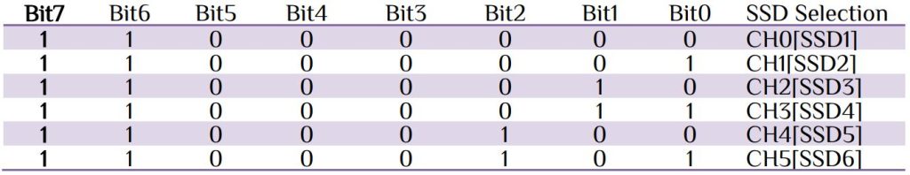
Since we use auto incremental method, so we need only one address 0xC0. We can control the brightness of the display.
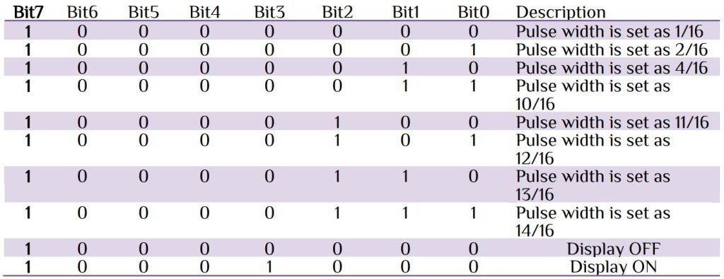
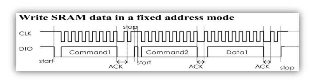
We can write at a fixed address with data. We use fixed address mode for display brightness control.
// Display control functions Brightness values: 1 - 7
void tm1637_SetBrightness(uint8_t brightness)
{
	tm1637_Start();
	tm1637_WriteByte(0x88+ (brightness&0x0f));
	tm1637_RACK();
	tm1637_Stop();
}
Once we set our brightness now it is time to display some data on the SSDs. Follow the step and send data in a sequence. For fixed address mode 0x44 and automatic address adding is 0x40.

void tm1637_DisplayUpdate(uint8_t data0,uint8_t data1,uint8_t data2,uint8_t data3)
{
//--- Send Data register
	tm1637_Start();
	tm1637_WriteByte(0x40);//Memory write command
    tm1637_RACK();
    tm1637_Stop();
//--- Send First address
    tm1637_Start();
    tm1637_WriteByte(0xC0);//Start address
    tm1637_RACK();
//---  Send Data 1 by 1
	tm1637_WriteByte(data0);//Data
    tm1637_RACK();
	tm1637_WriteByte(data1);//Data
    tm1637_RACK();
	tm1637_WriteByte(data2);//Data
    tm1637_RACK();
	tm1637_WriteByte(data3);//Data
    tm1637_RACK();
//--- Send Stop Condition for finished
    tm1637_Stop();
}
Our main program is to just display number and character.
#include <avr/io.h>
#include <util/delay.h>
int main(void)
{
    init_tm1637();
    while (1)
    {
		display_number(325,1);      // 4 digit number & 1 represents brightness level.
        _delay_ms(3000);
		display_char("Hello ..",1); // character available & 1 represents brightness level
        _delay_ms(3000);
    }
}
You can interface 6 digits using TM1637 IC. In that case you can build your own PCB display control seven segment display.


 Electronic Real Wrold


 Visit Today : 141
 Total Visit : 34318