

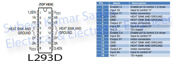
Let us control a motor using Fast PWM 8bit of Timer1. In order to control a 12V dc motor we need a driver IC that L293D.
In this program we use Timer1 OCR1A and OCR1B active at 8bit Fast PWM and two pin to control two dc motor. Here to control motor1 the driver has EN1 pin and we can change the direction by interchanging pin connection. Similarly to control motor2 the driver has EN2 pin and we can change the direction by interchanging pin connection. The two control pins are triggered simultaneously using INT0 external Interrupt. The control logic is-
TCCR1A|=(1<<WGM10)|(1<<COM1B1)|(1<<COM1A1);
/* Fast PWM non inverting prescalling 256*/
TCCR1B|=(1<<WGM12)|(1<<CS12);
sei();
//SREG|=(1<<I);//Globle interrupt enable
GICR |=(1<<INT0);			//External Interrupt Request 0 Enable
/********The rising edge of INT0 generates an interrupt request**/
MCUCR|=(1<<ISC00)|(1<<ISC01);
Parameter has been set. Now control 2 motors-

DDRB|=(1<<DDB1);    //OC1A Pin
OCR1A=115;          //45% duty cycle 8bit mode
PORTB&=~(1<<PINB3);
_delay_ms(500);
PORTB|=(1<<PINB0);

DDRB|=(1<<DDB2);   //OC1B Pin
OCR1B=153;         //60% duty cycle 8bit Mode
PORTB|=(1<<PINB3);
_delay_ms(500);
PORTB&=~(1<<PINB0);
Download the int0.c and int0.h file, the main program is as follow-
 #include<avr/io.h>
 #include<util/delay.h>
 #include<avr/interrupt.h>
 #include"int0.h"
uint16_t sample=1;
int main(void)
 {
   DDRB|=(1<<DDB0)|(1<<DDB3);//Control PIN
   int_int0();               //External Interrupt enable
   timer1();                 //Timer1 Enable
  while(1)
    {
        sample ? select2(): select1();
    }
  return 0;
 }
ISR(INT0_vect)
{
  sample^=0x01;
}

In AVR we can also generate sound using Timer. In this program we use an 8Ω speaker to generate sound which is connected to OC2 pin. Since OC2 pin of Timer2 can generate waveform and sound is nothing but a waveform. The Timer should operate in Fast PWM non-inverting mode with no prescalling and F_CPU=16HHz. The OCR2(duty cycle register) register’s value vary with the value stored in the flash memory. The main program as follow with ATmega8-
/***********************************************************************************************************************************
************************************************************************************************************************************
********************************* Sound Generation using PWM *************************************************************
************************************************************************************************************************************
		Subeer Kumar Sarkar
		Electrical & Electronic Engineer
************************************************************************************************************************************
************************************************************************************************************************************
***********************************************************************************************************************************/
#include<avr/io.h>
#include<util/delay.h>
#include<avr/pgmspace.h>
/************************** Sound Generation *****************************************/
const uint8_t sine[256]PROGMEM={
								127,130,133,136,139,143,146,149,152,155,158,161,
								164,167,170,173,176,178,181,184,187,189,192,195,197,200,203,205,
								207,210,212,214,217,219,221,223,225,227,229,231,232,234,236,237,
								239,240,242,243,244,245,246,248,248,249,250,251,251,252,253,253,
								253,254,254,254,254,254,254,254,253,253,253,252,252,251,250,250,
								249,248,247,246,245,243,242,241,239,238,236,235,233,231,229,227,
								225,224,221,219,217,215,213,210,208,206,203,201,198,195,193,190,
								187,185,182,179,176,173,170,167,164,161,158,155,152,149,146,143,
								140,137,134,131,128,125,121,118,115,112,109,106,103,100,97,94,91,
								88,85,82,79,76,73,71,68,65,62,60,57,55,52,50,47,45,42,40,38,36,34,
								31,29,27,26,24,22,20,19,17,15,14,13,11,10,9,8,7,6,5,4,3,3,2,2,1,
								1,0,0,0,0,0,0,0,1,1,1,2,2,3,4,4,5,6,7,8,9,10,12,13,14,16,17,19,
								21,22,24,26,28,30,32,34,36,39,41,43,45,48,50,53,55,58,61,63,66,
								69,72,74,77,80,83,86,89,92,95,98,101,104,107,110,113,116,119,122
							    };
/**********************************************************************************************/
uint8_t i;
int main(void)
{
/********************************Output PIN******************************************/
DDRB|=(1<<DDB3);						//oc2 pin connected
/****Timer Clock = CPU Clock (No Prescalling)  Mode = Fast PWM    PWM Output = Non Inverted******/
TCCR2|=(1<<WGM21)|(1<<WGM20)|(1<<COM21)|(1<<CS20);
/**********************************************************************************************/
while(1)
{
uint8_t delay,n;
/*******************************Control program**************************************/
	for(delay=1;delay<=50;delay++)
	{
		for(n=0;n<(51-delay);n++)
		{
			for(i=0;i<=254;i++)
			{
				OCR2=pgm_read_byte(&sine[i]);
				_delay_loop_2(delay);
			}
		}
	}
	for(delay=50;delay>=2;delay--)
		{
		for(n=0;n<(51-delay);n++)
			{
			for(i=0;i<=254;i++)
			{
				OCR2=pgm_read_byte(&sine[i]);
				_delay_loop_2(delay);
			}
		}
	}
/************************************************************************************/
}
return 0;
}
For 16HHz crystal setting The FUSE bit as follow-
HFUSE=0xc9 & LFUSE=0xEF


 Electronic Real Wrold


 Visit Today : 136
 Total Visit : 34313