
A servomotor is a rotary actuator that allows for precise control of angular position, velocity and acceleration. Most modern servomotor are designed and supplied around a dedicated control module. So that servomotor doesn’t require a driver. A microcontroller PWM pin can be used directly to control the servomotor.
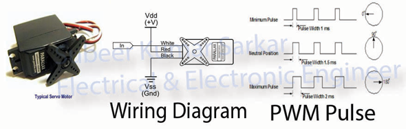
From picture it is seen that the servomotor works at 50Hz frequency. Let’s make a 50Hz frequency using Timer1 with Fast PWM.
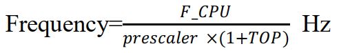
We know the frequency using Fast PWM
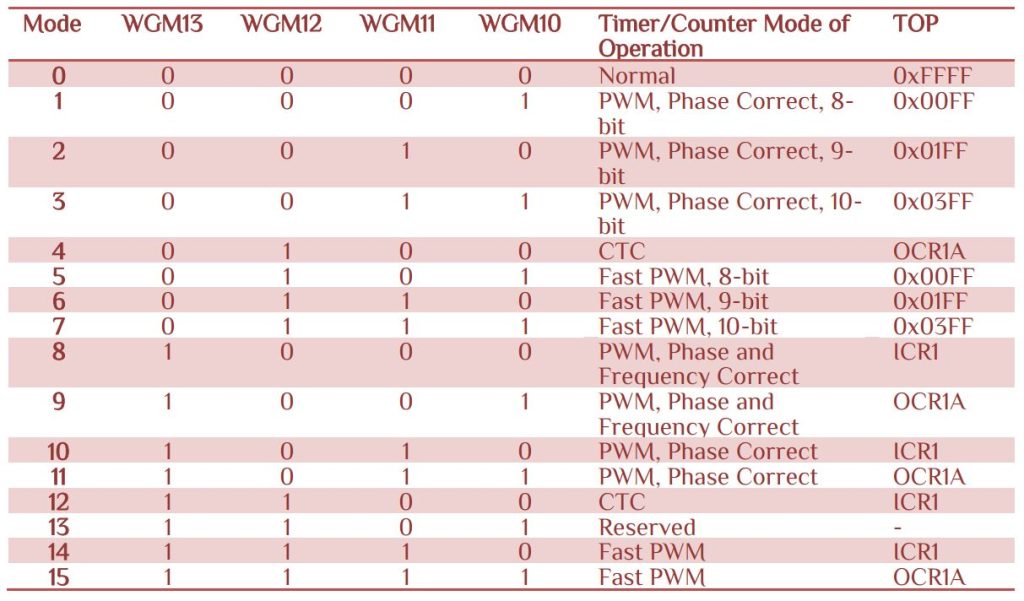
Let’s look at the Waveform Generation Mode Bit

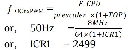
Let use Fast PWM with TOP value ICR1 with parameter F_CPU=8MHz and prescaler=64, than
The full program as follow-
/************************************************************************************************
*************************************************************************************************
*********************************** Servo Motor Control****************************************
*************************************************************************************************
		Subeer Kumar Sarkar
		Electrical & Electronic Engineer
************************************************************************************************
************************************************************************************************
***********************************************************************************************/
#include<avr/io.h>
#include<util/delay.h>
int main(void)
{
DDRB|=(1<<DDB1)|(1<<DDB2);									//OC1B & OC1A connected
/***********************Fast PWM TOP=ICR1 non-inverting mode************************************/
TCCR1A|=(1<<WGM11)|(1<<COM1B1)|(1<<COM1A1);
TCCR1B|=(1<<WGM13)|(1<<WGM12)|(1<<CS11)|(1<<CS10);		    //prescalling 64
ICR1=2499;													//time preiod 50Hz
/***********************************************************************************************/
while(1)
{
	for(int i=125;i<=249;i++)
	{
		OCR1B=i;
		_delay_ms(80);
	}

}
return 0;
}
Sometime you need to control multiple servomotors at the same time. In this case we need to set I/O port and clear I/O port in such meaner that a 50Hz pulse is generated. To generate a 50Hz pulse we use Fast PWM with TOP value ICR1, F_CPU=8MHz and prescaler=64. The coding is same for 50Hz frequency above. The next thing is to set I/O port at beginning and clear I/O port when we wanted. The trick is to set I/O port at interrupt and clear it in main program. In that procedure we can get our desire pulse. Let use Timer1 Compare A vector to set I/O port
/*************** Interrupt Enable ****************************/
#include<avr/interrupt.h>
sei();	//Global Interrupt Enable
TIMSK|=(1<<OCIE1A);  //Timer1, Output Compare A Match Interrupt Enable
/*********************   Set logic  ****************************/
ISR(TIMER1_COMPA_vect)
{
   //set I/O port
}
Now the clear logic is to check the TCNT1 value and define a TCNT1 condition to clear each I/O ports. A simple C code as follow-
if(TCNT1>=140 && TCNT1<=249)
  {
   if(TCNT1>=140) PORTx &=~(1<<PINx);
   if(TCNT1>=180) PORTx &=~(1<<PINx);
-------------------------------------------------------------
  }
The complete program as follow-
/****************************************************************************************************
*****************************************************************************************************
***************************** Multiple Servo Motor Control ******************************************
*****************************************************************************************************
		Subeer Kumar Sarkar
		Electrical & Electronic Engineer
******************************************************************************************************
******************************************************************************************************
*****************************************************************************************************/
#include<avr/io.h>
#include<util/delay.h>
#include<avr/interrupt.h>
int main(void)
{
DDRD|=0x0f;
/********************************Fast PWM  prescalling 64*********************************************/
TCCR1A|=(1<<WGM11);            						   //Normal port operation, OC1A/OC1B disconnected
TCCR1B|=(1<<WGM13)|(1<<WGM12)|(1<<CS10)|(1<<CS11);
TIMSK|=(1<<OCIE1A);									   //Timer1, Output Compare A Match Interrupt Enable
sei();													   //Globel Interrupt Enable
ICR1=2499;										           //Time preiod 50Hz
/******************************************************************************************************/
while(1)
{
/**************************************** Clear Logic *************************************************/
if(TCNT1>=140 && TCNT1<=249)
{	if(TCNT1>=140) PORTD &=~(1<<PIND0);
	if(TCNT1>=180) PORTD &=~(1<<PIND1);
	if(TCNT1>=200) PORTD &=~(1<<PIND2);
	if(TCNT1>=240) PORTD &=~(1<<PIND3);
}
/*******************************************************************************************************/
}
return 0;
}
/*************************************** Set Logic *****************************************************/
ISR(TIMER1_COMPA_vect)
{
PORTD=0x0f;
}
/*******************************************************************************************************/
For crystal setting The FUSE bit as follow-
HFUSE=0xc9 & LFUSE=0xEF


 Electronic Real Wrold


 Visit Today : 132
 Total Visit : 34309
1 thought on “Servo Motor Control”
Comments are closed.