
Most of the real world sensor output is analog type. We can read the analog output with the ADC pin provided in Atmel family. In ATnega32 there are 8 ADC channel with 10bit resolution. That means each of the ADC channel can divide 0-5V to 0-1023 counting value that can be easily read by the ALU unit. So the resolution in terms of voltage is-
resulation=(5/1024)≈5mV
Now what is the adc value of 2.5V? For single ended conversion, the ADC result is
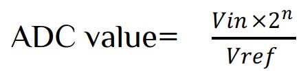
Where Vin= analog voltage input & Vref= Voltage reference
So if the sensor value Vin=2.5 and Vref=5V, than ![]()
Since in C the counting begin from 0, the value should be ADC value=511. Let’s look at the register available for ADC in ATnega32 and there uses-
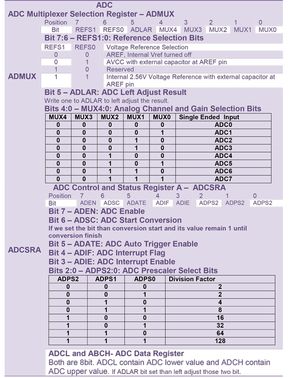
To work with ADC we have to do two things
- ADC Initialization
- ADC result.
- ADC reference selection
- ADC clock selection to make the F_ADC=50kHz-200kHz
- ADC Enable
Suppose we want to initialize Vref=AVCC(5V) and use a crystal of 16MHz. Now to enable AVCC with external capacitor (100nf) at AREF pin
ADMUX|=(1<<REFS0);
For F_ADC=(F_CPU/Prescaler), here we want F_ADC=125kHz, than > Prescaler=(16MHz/125kHz)=128
ADCSRA|=(1<<ADPS2)|(1<<ADPS1)|(1<<ADPS0);
For ADC Enable : ADCSRA|=(1<<ADEN);
Let’s use a user-defined function that has no argument and no return function i.e. void adc_init (void). So our C code for ADC initializing is-
  ADMUX|=(1<<REFS0);//AVCC with external capacitor at AREF pin
  ADCSRA|=(1<<ADPS2)|(1<<ADPS1)|(1<<ADPS0);
  ADCSRA|=(1<<ADEN);

- ADC Channel selection
- ADC start conversion
- wait until conversion finished
- Read the ADC value
Let use a user defined function that use an 8 bit argument value (for channel) and 16bit return value (since ADC is 10bit).
 uint16_t read_adc(uint8_t ch)
{
 uint8_t channel;
 channel=0xff&ch;  // Filter channel
 ADMUX=(ADMUX & 0xc0); //Clear all channel
 ADMUX|=channel;//Analog Channel Selection
 ADCSRA|=(1<<ADSC);//ADC Start Conversion
while(ADCSRA &(1<<ADSC))
 {
   ;//do nothing until conversion finished
 }
 return (ADCW);
}
Note that as soon as we enable the ADSC bit of ADCSRA register, ADC conversion start. This bit is clear when the conversion over. So in the while loop we check the condition of bit set. If it is clear than return it in unsigned 16bit integer.
ADC with Interrupt
ADC can also be read using ADC interrupt. In that case the interrupt trigger as soon as the conversion compete. Let’s display ADC 8bit value in I/O port of AVR. In that case we use interrupt driven ADC. In that case we make some changes in both ADC initialization and ADC read condition
ADC Initialization
 void adc_init(void)
{
ADMUX |=(1<<REFS0);								//AVCC with external capacitor at AREF pin
ADCSRA |=(1<<ADPS2)|(1<<ADPS1);					//F_ADC=F_CPU/64
ADCSRA |=(1<<ADEN);								//ADC Enable
ADCSRA |=(1<<ADIE);								//ADC Interrupt Enable
sei();												//Global Interrupt Enable
}
Here F_CPU= internal 8MHz. ADC read function using interrupt
 void adc_value(uint8_t Ch)
{
uint8_t channel;
channel=0xff&Ch;									//Filter Channel
ADMUX=(ADMUX & 0XC0);								//Clear all channel
ADMUX |=channel;									//Analog Channel Selection
ADCSRA |= (1<<ADSC);								//ADC Start Conversion
}
The main program as follow-
 #include<avr/io.h>
 #include<util/delay.h>
 #include<avr/interrupt.h>
 #include"adc.h"
 uint16_t value;
int main(void)
{
  DDRD=0xFF; 						//PORTD for output
  adc_init();						//ADC Initilization
  while(1)
	{
	  adc_value(0);				//Read ADC Channel 0
	  PORTD=(uint8_t)value;		//PORTD=ADCL
	}
 return 0;
}
ISR(ADC_vect)
{
  value=ADCW;
}


 Electronic Real Wrold


 Visit Today : 132
 Total Visit : 34309