
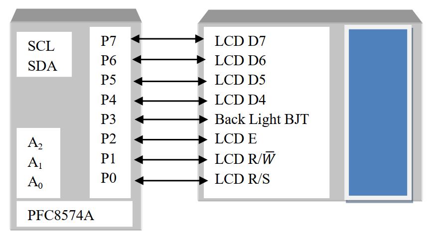
We already learn LCD interfacing in GPIO part. LCD Display requires lots of digital I/O pin and the circuit requires more space. In market I2C LCD display are available and the interfacing is not so difficult. You just need the hardware and the I2C IC which is connected with that LCD. Usually in maximum I2C LCD module use PFC8574A. The PCF8574A is a I2C parallel port expander with latch outputs with high-current drive capability for directly driving LEDs. First look at the hardware how it is connected to LCD.
Here pins A2:A1 are connected to Vcc via 1KΩ resistance. SDA and SCL are internally pull-up by Vcc so no need for an extra pull-up resistors. Let’s look at the I2C protocol provide by datasheet
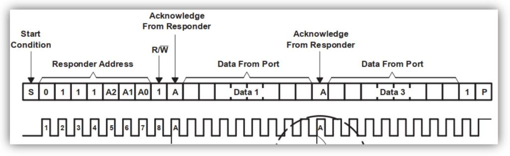
Here the logical address is 0111 and the physical address is 111 (since all pin are connected to Vcc). So the device has I2C address 0b0011 1111 or 0x3F. From the data sheet provided we need to start I2C then write the device address with write operation and send data. So our first step is to initialize the LCD ones with I2C start and device ADD+W then we just send data, no farther need of I2C start and device ADD+W command. We just need to change some user function in the LCD library. Let’s go step by step. Since the device can work with 100KHz frequency.
void system_init(void) -> I2C initialization function
void system_init(void)
{
  TWSR=0x00;                //--- Presclar = 1=4^0
  TWBR=0x20;                //--- F_CPU=8MHz and Prescaler=1
  TWCR=(1<<TWEN);           //--- TWI Initialazion
  TWCR=(1<<TWEN)|(1<<TWINT)|(1<<TWSTA); //--- TWI Interrupt desable, TWI enable, TWI Start
  while(!(TWCR&(1<<TWINT)));             //--- Wait untial start condition is executed
  twi_write(0x3F<<1 | 0);  //PCF8574A---- Device ID-- 0b0111 1110
  LCD_INIT();              //LCD Initializion
  _delay_ms(100);          //Some delay for LCD initialization
}
Let’s look the write command or data function. For write command the R/S pin remain 0 and EN pin goes from 1 to 0.
void LCD_cmd(unsigned char cmd) -> write command format
void LCD_cmd(unsigned char cmd)
{
  twi_write(cmd|0b00001100); // EN = 1 and Backlight ON(Pin –P3)
  _delay_ms(2);
  twi_write(cmd|0b00001000); //EN = 0 and Backlight ON
}
void nibble_cmd(unsigned char LCD_value) -> write command
void nibble_cmd(unsigned char LCD_value)
{
  unsigned char display_nibble;
  display_nibble=LCD_value&0xF0;                 //mask lower nibble because DD4-DD7
  pins are used
  LCD_cmd(display_nibble);                       //Send upper Nibble
  display_nibble=((LCD_value<<4) & 0xF0);       //mask the upper Nibble
  LCD_cmd(display_nibble);
}
Now for data send R/S pin is 1 and EN pin goes from 1 to 0.
void LCD_write(unsigned char data) -> write data format
void LCD_write(unsigned char data)
{
  twi_write(data|0b00001101); // EN = 1, R/S=1 and Backlight ON
  _delay_ms(2);
  twi_write(data|0b00001001); // EN = 0, R/S=1 and Backlight ON
}
void nibble_data(unsigned char LCD_data) -> write data
void nibble_data(unsigned char LCD_data)
{
  unsigned char data_nibble;
  data_nibble=LCD_data&0xF0;                   //mask lower nibble because DD4-DD7 pins are used
  LCD_write(data_nibble);                      //Send upper Nibble
  data_nibble=((LCD_data<<4) & 0xF0);         //mask the upper Nibble
  LCD_write(data_nibble);
}
LCD other function remain the same. Download the I2CLCD.c and I2CLCD.h file, the main program as follow-
  #include<avr/io.h>
  #include<util/delay.h>
  #include<util/twi.h>
  #include"I2CLCD.h"
int main(void)
  {
   system_init();
   LCD_write_string(1,2,"RUET EEE 091109");
   while(1)
     {
       LCD_write_string(1,1,"Subeer kumar Sarkar");
       _delay_ms(500);
       LCD_Display_Right();
     }
 return 0;
}
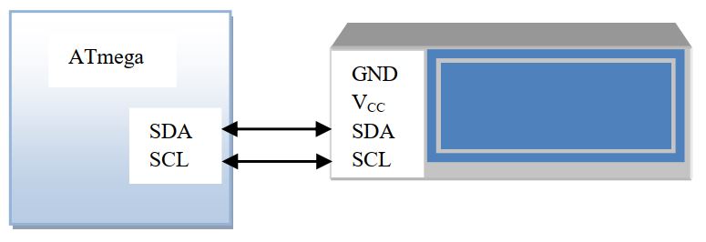
If you don’t see the character on the display rotates the potentiometer of the I2C LCD. The connection as shown in the figure.


 Electronic Real Wrold


 Visit Today : 135
 Total Visit : 34312