
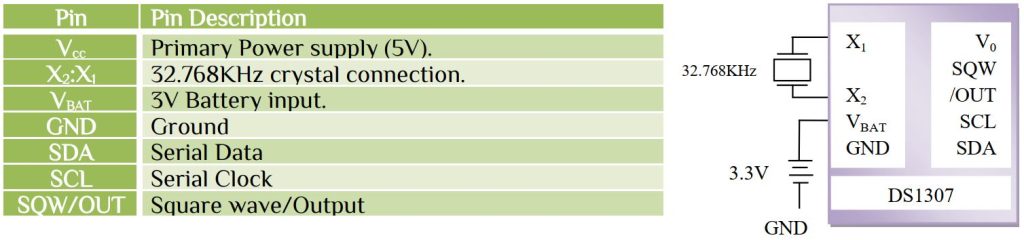
The DS1307 serial real time clock is a low power, full binary-coded decimal (BCD) clock/calendar plus 56bytes of NV SRAM. Address and data are transmitted serially via 2-wire, bi-directional bus. The clock/calendar provides seconds, minutes, hour, day, date, month and year information. The end date at the month date is automatically adjusted for months with fewer than 31days, including correction for leap year. The clock operates in either the 24 hours or 12 hours format with AM/PM indicator. The DS1307 has a build in power sense circuit that detects power failures and automatically switches to the battery supply.
Controlling clock register
Here the 07H address is used to control the operation of the SQW/OUT pin.
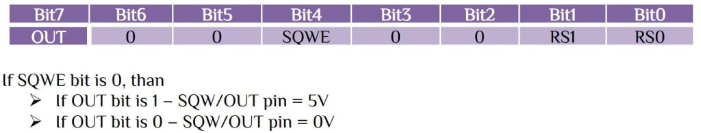
If SQWE bit is 0, than
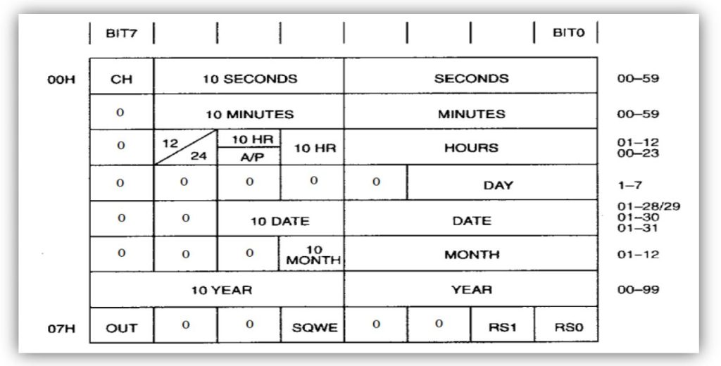
Now the first step is to initialize the RTC with seconds, minutes, hours, day, date, month, year and output we want. RTC works on BCD format.
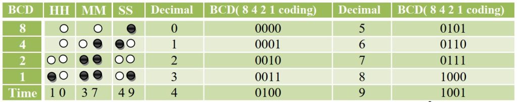
Here the time is 10:37:49 or in BCD format 0x10:0x37:0x49. Let’s look at the I2C protocol for data writing procedure-
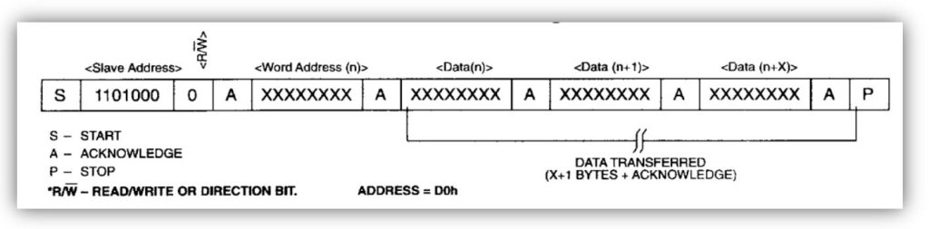
Here the slave address is 0b0110100 or 0x34. The address byte has auto increment value. The first address is 0x00 which is seconds. The function is-
uint8_t I2C_Write_RTC(uint8_t min,uint8_t hr,uint8_t day,uint8_t date,uint8_t month,uint8_t year)
#define RTC_Write_Addess 0xD0 //0b11010000
uint8_t I2C_Write_RTC(uint8_t min,uint8_t hr,uint8_t day,uint8_t date,uint8_t month,uint8_t year)
{
I2C_Start(); // Start condition
I2C_Write(RTC_Write_Addess);
I2C_Write(0x00); // For intial address 0x00
I2C_Write(0); // Initial Second for value 0
I2C_Write(min); // Write Minute value
I2C_Write(hr); // Write hour value
I2C_Write(day); // Write day value 0 for Sunday
I2C_Write(date); // Write date of month
I2C_Write(month);// Write month value
I2C_Write(year); // Write year value
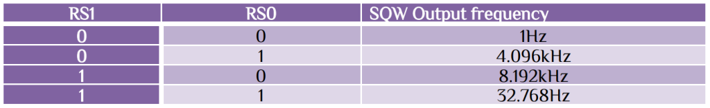
I2C_Write(0x90); // Square wave with 1Hz output
I2C_Stop();
}
Example: write the time 10:37am 16/11/23 Thursday is

In C we can’t return multiple values from a function directly. We can return more than one values from a function by using the method “called by address” or “call by reference”. In the invoke function, we can use two variables to store the results and the function will take pointer data type. So we have to pass the address of the data. We use this return method function to read the date and time from RTC. First look the I2C protocol for read from RTC-
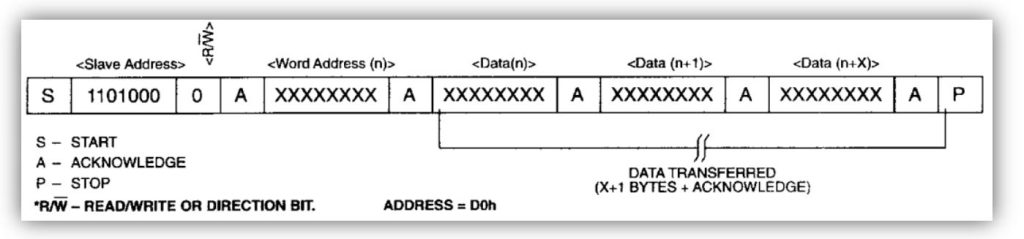
The read from 0x00 register and we use multiple return function using pointer-
uint8_t I2C_Read_RTC(int *sec, int *mi, int *hr, int *da, int *dat, int *mon, int *yr)
#define RTC_Read_Addess		0xD1 //0b11010001
uint8_t I2C_Read_RTC(int *sec, int *mi, int *hr, int *da, int *dat, int *mon, int *yr)
{
    I2C_Start();
	I2C_Write(RTC_Write_Addess);
	I2C_Write(0x00);
	I2C_Start();
	I2C_Write(RTC_Read_Addess);
	*sec=I2C_Read_Ack();
	*mi=I2C_Read_Ack();
	*hr=I2C_Read_Ack();
	*da=I2C_Read_Ack();
	*dat=I2C_Read_Ack();
	*mon=I2C_Read_Ack();
	*yr=I2C_Read_Nack();
	I2C_Stop();

}
The reading procedure is from main function, where we call the function we create.
volatile int second,minute,hour,day,date,month,year;
I2C_Read_RTC(&second,&minute,&hour,&day,&date,&month,&year);
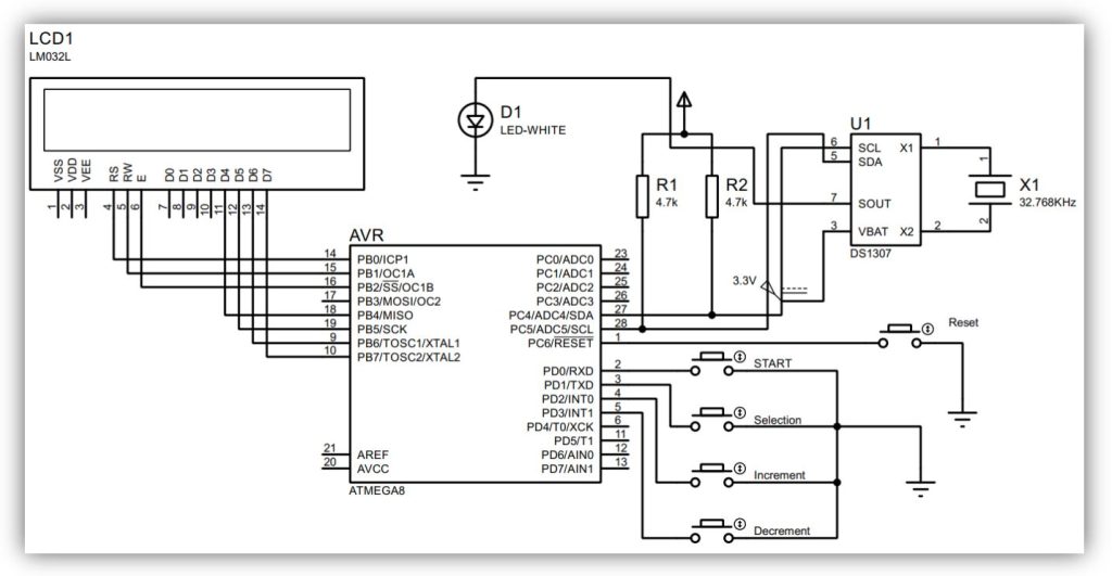
From the function second, minute, hour, day, date, month and year represent the real time value. Let’s go back to the datasheet, address 0x02 bit 6 represent the 12/24 hour mode and bit 5 represent the am/pm mode. If we select 24 hour mode then no need for am/pm. But if we set 12 hour mode then we must read the 5th bit for am/pm count. You have learn how the RTC works and how to read. We make a program to select the desire time and select the start button to start your RTC clock. Here just look at the pin and their function -> MCU: ATmega8
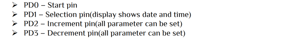
Set your parameter and press start for RTC clock, the data will show in LCD display. Follow the connection diagram.


 Electronic Real Wrold


 Visit Today : 136
 Total Visit : 34313