
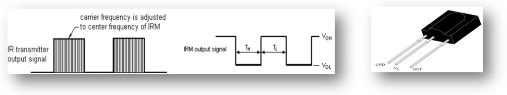
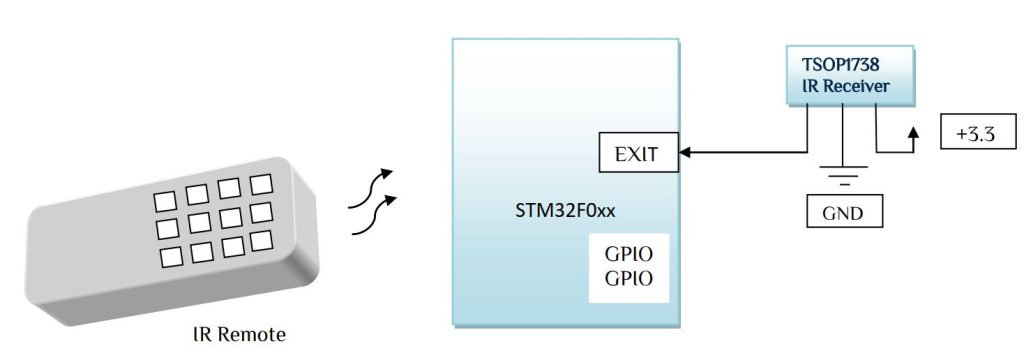
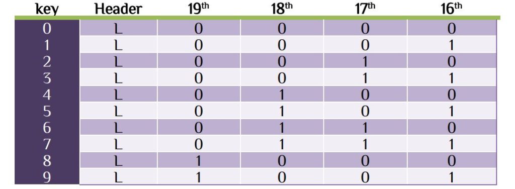
Sometime we want to turn on/off some load using a remote. Audio, TV, AC remote available in market, which works on AM modulated signal. That when any key pressed, a burst of AM modulated signal send through IR transmitter. In AM modulated signal the carrier signal may be 30kHz/36kHz/38kHz/56kHz. In market may IR Decoder IC available, but in our case we use TSOP1738. The IR receiver sensor works at active low, means if any IR signal of 38K AM modulated wave found the output of the IR receiver is GND otherwise it high all time. When any key pressed a brunch of data is send in form of 38K AM modulated signal. Following is the data send from remote.
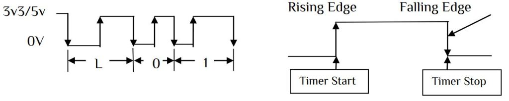
Here L defines as line code and 0 and 1 represented as low pulse and high pulse.
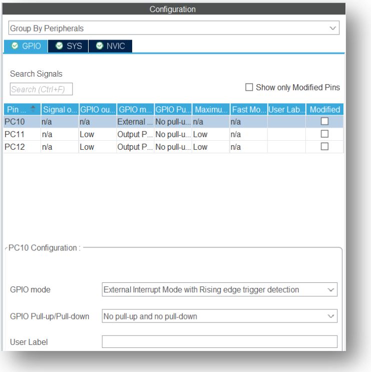
We have learn some basic idea now let’s start with a remote. In my house I find an old TV remote. Let’s start with this remote, from the IR decoding principle our first step is enable a GPIO pin with EXIT with rising edge & falling edge detection with interrupt. In our example we use 2 GPIO pin for output pin. If 1 key is pressed GPIO pin toggle & if 2 key is pressed then another GPIO pin will toggle. That every time 1/2 key pressed a corresponding load on/off. For detecting pulse we need a timer. Our logic is-

In our previous article we learn some basic timer function. We will enable a timer with 1us clocking. Let’s look at some settings-
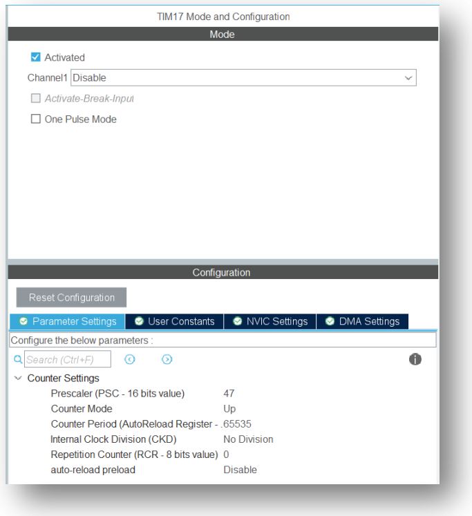
Here the APB1 timer clock is 48MHz. Enable the global interrupt for EXIT with rising/falling edge and we will programmer file is Interrupt generated c file. No program in main file. The interrupt file is something like stm32f0xx_it.c. We separate our program in 2 steps. First we detect the line code pulse, 1 pulse & 0 pulse duration. For our simplicity we use large duration pulse as 1 pulses & short duration pulse as 0 pulses. 1st program –
extern TIM_HandleTypeDef htim17;
uint32_t pulse_width;
uint8_t flag=1,counter;
uint16_t data_packet[96];
if(flag)
  {
    pulse_width=TIM17 -> CNT ; // counter value
	data_packet[counter++]=pulse_width;
	TIM17->CNT=0;              // restart counter(optional)
	flag=0;
  }
  else
  {
   HAL_TIM_Base_Start(&htim17); // start timer
   flag=1;
   TIM17->CNT=0;                // start counter with value 0
  }
Here we use timer 17 as pulse duration and void EXTI4_15_IRQHandler(void) function for code detection. In our case maximum 96 pulses will count in any 36kHz IR signal. It very simple program for detect pulse wide and number of pulses. In my case I found header code around 4520us, digital 1 signal around 1645us, a digital 0 signal around 540us. Let’s modify our program with header code and 1&0 bit with the help of pulse duration.
#define HEADER_CODE_START 4500    // Change according to IR Line Code
#define HEADER_CODE_END   4600    // Change according to IR Line Code
#define LOGIC_HIGH_START  1600    // Change according to BIT 1 Code
#define LOGIC_HIGH_END    1700    // Change according to BIT 1 Code
#define LOGIC_LOW_START   500     // Change according to BIT 0 Code
#define LOGIC_LOW_END     600     // Change according to BIT 0 Code
#define MAX_BIT           32      // Change according to Number of bit received
uint16_t pulse_width;
uint8_t flag=1,u8_header,IR_Code[MAX_BIT];
int counter;
if(flag)
  {
        pulse_width=TIM17 -> CNT ;
		if(pulse_width>HEADER_CODE_START && pulse_width<HEADER_CODE_END) {u8_header=1;counter=-1;}
		if(u8_header){
		if(pulse_width>LOGIC_HIGH_START && pulse_width<LOGIC_HIGH_END)IR_Code[counter]=1;
		else if(pulse_width>LOGIC_LOW_START && pulse_width<LOGIC_LOW_END)IR_Code[counter]=0;
		counter++;
		if(counter>(MAX_BIT-1)){
			// Your control logic here
			u8_header=0;
		              }
		}
		TIM17->CNT=0;
		flag=0;
  }
  else
  {
   HAL_TIM_Base_Start(&htim17);
   flag=1;
   TIM17->CNT=0;
  }
Change the parameter in the defined section. The remote transmit only 1 line code and 32bits of 1&0. Please note that IR also transmit footer code/ end code. In 32 bit there will be some header code & checksum bits. Every key has its unique 32bit code. It’s very difficult to set logic of 32bits, so we have to experiment the data in the debug section and note down every key pressed data. In my measurement I found a bit pattern in 0 to 9 key pressed. The data I found-
In my case I use PC10 as EXIT pin, PC11 & PC12 as GPIO Outputs pins. If key 1 is pressed PC11 will toggle & if key 2 is pressed PC12 will toggle. In 2nd part of program we introduce a comment for your logic, use it for your load control as follow-
/*****                       load condition             **********************/
	if(IR_Code[19] ==0 && IR_Code[18]==0 && IR_Code[17] ==0 && IR_Code[16]==1)
	HAL_GPIO_TogglePin(GPIOC,GPIO_PIN_11); //key 1 pressed
	if(IR_Code[19] ==0 && IR_Code[18]==0 && IR_Code[17] ==1 && IR_Code[16]==0)
	HAL_GPIO_TogglePin(GPIOC,GPIO_PIN_12); //key 2 pressed
/*****************************************************************************/
The final program is based on the first program experimental data. The STM32 has strong debug feature, so that no need an external oscilloscope. In any remote first detect the signal code then make your changes. An AC remote is an organized remote with different function like fan, temperature, ionization, load control etc. In this article we are not decode all the function of a remote, just use it as a simple load control.


 Electronic Real Wrold


 Visit Today : 132
 Total Visit : 34309