
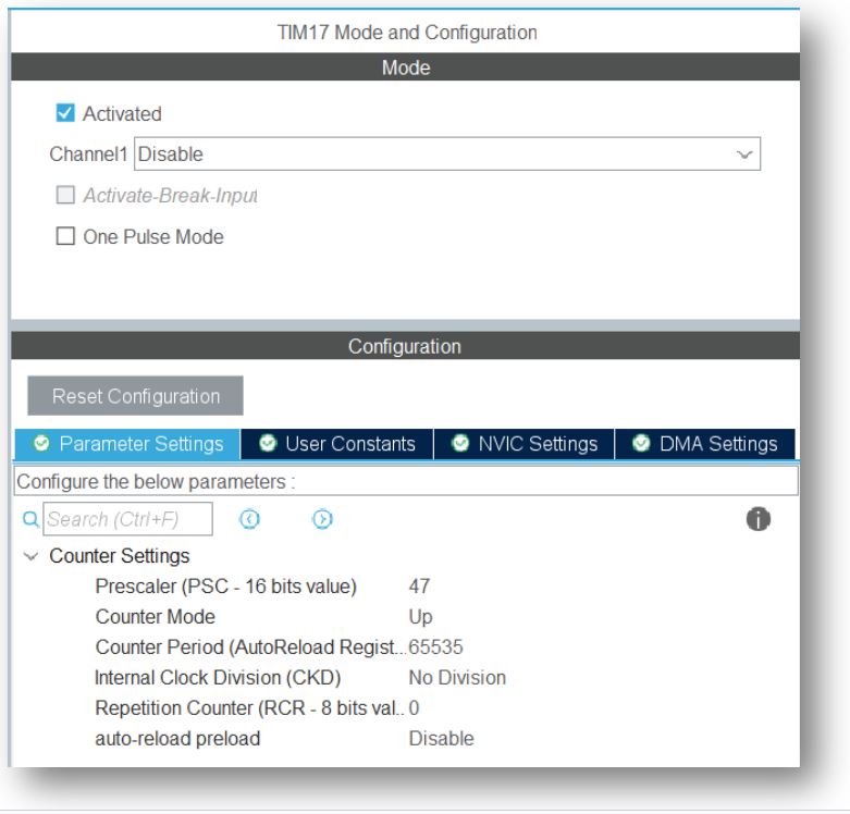
In STM32 there are different types of timer i.e. Advanced-control timer, General-purpose timers, Independent watchdog timer, Window watchdog timer. Example in STM32F030x8 mcu uses APB1 Timer Clocks for Advanced-control timer & General-purpose timers. In HAL_Delay function we can only have 1ms delay system delay. We will use TIM17 general purpose time to create 1us delay. Let’s use system clock as 48MHz fsys = 48MHz and prescaler value 47, so the new clock frequency for TIM17 is-
fTIM17 = fsys / (prescaler +1) = 48MHz/(47+1) = 1MHz & tTIM17 = 1us
So that the Counter Period (Auto Reload Register) will be update in every 1us value. The Couter Period has a maximum value of 216-1 or 65535. So the logic is-
void _delay_us(uint8_t delay)
{
HAL_TIM_Base_Start(&htim17);
__HAL_TIM_SET_COUNTER(&htim17,0);  // set the counter value a 0
while (__HAL_TIM_GET_COUNTER(&htim17) < delay);  // wait for ARR value
}
Some useful function of timer as follow-
HAL_TIM_Base_Start(TIM_HandleTypeDef *htim);      // start timer
HAL_TIM_Base_Stop(TIM_HandleTypeDef *htim);       // stop timer
HAL_TIM_Base_Start_IT(TIM_HandleTypeDef *htim); // start timer with interrupt
HAL_TIM_Base_Stop_IT(TIM_HandleTypeDef *htim);  // stop timer with interrupt
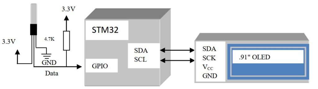
Here we interface DS18B20 digital temperature sensor with PC0 pin of STM32F0308-DISCO board. Before start please go through my DS18B20(Digital Temperature Sensor) interfacing with GPIO article, because we will not discuss the interfacing logic. Here we just change some parameter according to STM32 HAL Library. In STM32CubeMX we just initialize the GPIO as input or output configuration. But in DS18B20 sensor interface we need to set the same GPIO pin as input and output. So to define a GPIO pin as output or input will be-
#define DS18B20_GPIO              GPIOC
#define DS18B20_PIN               GPIO_PIN_0
void output(void)
{
  GPIO_InitTypeDef GPIO_InitStruct = {0};
  GPIO_InitStruct.Pin = DS18B20_PIN;
  GPIO_InitStruct.Mode = GPIO_MODE_OUTPUT_PP;
  GPIO_InitStruct.Pull = GPIO_NOPULL;
  GPIO_InitStruct.Speed = GPIO_SPEED_FREQ_LOW;
  HAL_GPIO_Init(DS18B20_GPIO, &GPIO_InitStruct);
}
void input(void)
{
  GPIO_InitTypeDef GPIO_InitStruct = {0};
  GPIO_InitStruct.Pin =  DS18B20_PIN;
  GPIO_InitStruct.Mode = GPIO_MODE_INPUT;
  GPIO_InitStruct.Pull = GPIO_PULLDOWN;
  HAL_GPIO_Init(DS18B20_GPIO, &GPIO_InitStruct);

}
So change in reset function as follow-
#define CONFIG_OUTPUT             HAL_GPIO_WritePin(GPIOC,GPIO_PIN_0,GPIO_PIN_RESET)
#define READ_INPUT                HAL_GPIO_ReadPin(GPIOC,GPIO_PIN_0)
uint8_t DS18B20Reset(void)
{
	//Pull Output line low and wait for 480uS
    output();//Output low for 480us
    CONFIG_OUTPUT;//Configure as Output
	_delay_us(480);
	//Release line and wait for 60uS
    input(); //Configure as Input
	_delay_us(60);
	//Store line value and wait until the completion of 480uS period
	uint8_t i;
	i=(READ_INPUT);
	_delay_us(420);
	return i; //Return the value read from the presence pulse (0=OK, 1=WRONG)
}
Similarly change in sensor read & sensor write functions-
void DS18B20Write(uint8_t byte)
{
	for(uint8_t i=0;i<8;i++)
	{
	  //Pull line low for 2uS
      output();  //Configure as Output
      CONFIG_OUTPUT;//Output low
	  _delay_us(2);
	  //If we want to write 1, release the line (if not will keep low)
	  if(byte & 0x01) input();
      //Configure as Input
	  _delay_us(60);
      input(); //Configure as Input
	  _delay_us(1);
	  byte=byte>>1;
	}
}
uint8_t DS18B20Read()
{
	uint8_t byte=0x00;
	for(uint8_t i=0;i<8;i++)
	{
	  byte=byte>>1;
	  //Pull line low for 1uS
      output(); //Configure as Output
      CONFIG_OUTPUT; //Output low for 2us
	  _delay_us(2);
	  //Release line and wait for 14uS
      input();
	  _delay_us(14); //Configure as Input
	  if(READ_INPUT) byte|=0x80;
	  _delay_us(45);
	}
	return byte;}
No change in DS18B20ReadTemp function. All functions are ready, now it is time to download the driver file and display it. In display part we use .91 ” OLED. You can change GPIO pins in the definition section & use the driver library.


 Electronic Real Wrold


 Visit Today : 132
 Total Visit : 34309