
In ATmel section we learn about watchdog timer. In STm32 we have system window watchdog (WWDG) & independent watchdog (IWDG). Not all STm32 family has IWDG feature but all have WWDG feature. The system window watchdog (WWDG) is used to detect the occurrence of a software fault, usually generated by external interference or by unforeseen logical conditions, which causes the application program to abandon its normal sequence.
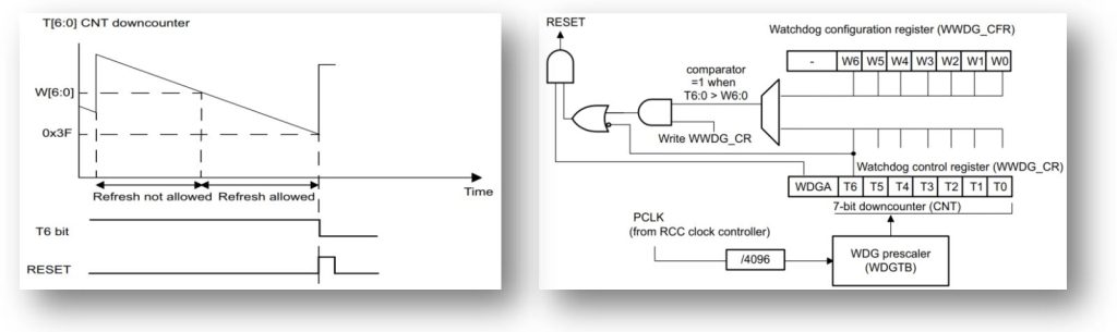
It is basically a window were you have to refresh the counter otherwise the mcu will reset. The formula to calculate the timeout value is given by:
tWWDG = tPCLK x 4096 x2WDGTB[1:0] x (T[5:0]+1) (ms)
Here tWWDG: WWDG timeout & TPCLK: APB clock period measured in ms
As an example, lets assume APB frequency is equal to 48 MHz, WDGTB[1:0] is set to 3 and T[5:0] is set to 63, the window minimum time will be
tWWDG = (1/48000)*4096*23*(63+1) = 43.69ms ~ 43ms
The maximum window value will be at T = 127 ,
tWWDG = (1/48000)*4096*23*(127+1) ~ 87ms
Thus if we refresh after 43ms the program will flow otherwise the mcu will reset continuously & the range from 43ms to 87ms. Hall library function to refresh-
HAL_WWDG_Refresh(&hwwdg); // refresh WWDG
IWDG : The devices feature an embedded watchdog peripheral that offers a combination of high safety level, timing accuracy and flexibility of use. The Independent watchdog peripheral detects and solves malfunctions due to software failure, and triggers system reset when the counter reaches a given timeout value.
The independent watchdog (IWDG) is clocked by its own dedicated low-speed clock (LSI) and thus stays active even if the main clock fails.
The formula to calculate the timeout value is given by:
tIWDG = tLSI x 4 x 2PR x (RL +1)
Where tLSI is low-speed clock (LSI) frequency and PR & RL are fields of IWDG registers. In our timer basic section we learn to interface digital temperature sensor DS18B20. Let look at the datasheet of STm mcu, there is a dedicated fLSI = 40kHz. If the prescaler for LSI clock 16, then every counting frequency will be 2.5kHz and time 0.4ms. If we set counting value 212 or 4096 then maximum time to reset will be 1.6384s.
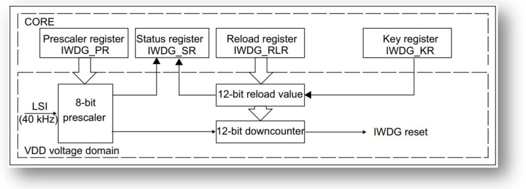
fLSI = 40kHz & prescaler 16 , then new fLSI = 2.5kHz , tLSI = 1/fLSI = 0.4ms and RL = 4095,
tIWDG = 0.4ms * (RL+1) = 0.4 x 10-3 * (4095+1) = 1.6384s
If we activate IWDG at prescaler 16, fLSI 40kHz & counter reload value 4095, then we have 1.6384s to read the sensor data & refresh the counter. If the counter will not refresh within 1.6s the microcontroller halt and restart again & again. Hall library function to refresh-
HAL_IWDG_Refresh(&hiwdg); // refresh IWDG Counter
The other logic will be same in timer section one additional part is to activate IWDG timer with the above parameter. In my example I used I2C1 for OLED & GPIOB-> PINB5 for sensor reading. The main program as follow (only the change parameter)-
#include "ssd1306.h"
#include "ds18b20.h"
  uint8_t temp;
  char display[16];
  init_OLED();
  clear_display();
  OLCD_write_string(0,0,"iotthinghub.com");
  OLCD_write_string(2,0,"Connecting Sen..");
  HAL_Delay(1000);
  MX_IWDG_Init();
while (1)
  {
      temp=DS18B20ReadTemp();
      if(temp) HAL_IWDG_Refresh(&hiwdg);
      else OLCD_write_string(2,0,"Sensor Missing.."); //This line will not execute
      if(temp) sprintf(display,"Tem:%.4f C   ",temperature);
      OLCD_write_string(2,0,display);
  }
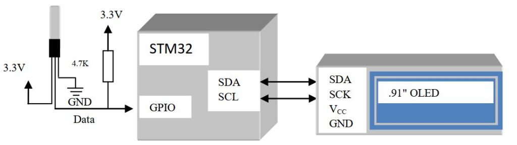
Connect as shown in the diagram, if you disconnect the GPIO pin PINB5 the mcu will restart again & again. By modification the program GPIO & I2C you can used it in any STm32 microcontroller.


 IoTthingHuB


 Visit Today : 58
 Total Visit : 41174