
In ATmel section we learn about ADC (Analog to Digital Converter). In AVR microcontroller we have 10bit ADC: 210 , but in STm microcontroller we have 12bit ADC: 212. In AVR we have 5V as reference voltage that’s work on most sensors, but in STm microcontroller we have ref voltage 3.3V. The voltage 3.3V divide into 0 to 212-1 or 0~4095. So the ADC output voltage-
Vout = ( Vin x(2n -1))/ Vref , here n=12 & Vref = 3.3V
Vout = ( Vin x 4095)/3.3 V
ADC can 12-bit, 10-bit, 8-bit or 6-bit configurable resolution; 1.0 µs for 12-bit resolution (1 MHz), 0.93 µs conversion time for 10-bit resolution, faster conversion times can be obtained by lowering resolution, DMA support. Most ST has internal temperature sensor (VSENSE) & internal reference voltage (VREFINT). It has some mode of conversion like; can convert a single channel or can scan a sequence of channels, single mode converts selected inputs once per trigger, continuous mode converts selected inputs continuously, discontinuous mode. Interrupt generation at the end of sampling, end of conversion; end of sequence conversion, and in case of analog watchdog or overrun events. It has also analog watchdog feature. In this article we discuss about NTC sensor for temperature measurements using ADC discontinuous mode with 12bit resolution with suitable sampling time.
There are basically 2 type of sensor NTC & PTC. NTC stands for negative temperature coefficient, and its resistance decreases as its temperature increases. PTC stands for positive temperature coefficient, and its resistance increases as its temperature increases. PTC thermistors are used to protect sensitive components or devices from damage due to over current or short circuits. They can automatically shut off and reset themselves when over-current conditions occur. NTC temperature sensors are mostly used in fridge or AC. It is a low cost sensor & easy to implement. It is nothing but a variable resistor that resistance increase as temperature decreases. For calculating temperature we just need 2 values Resistance at 25 C & Beta Value B (25/50). In my case –
- Resistance at 25C R25: 5000 ohm+/-2%
- Beta Value B(25/50): 3950K+/-1%
The room temperature defines the xK ohm, where xK may be 10K, 20K etc. The data sheet provide the Beta value, that we will have to know. Calculation the temperature value in Kelvin, the formula is-
Temperature in Kelvin, Tmeasure =1/(ln(Rk/Rntc)/B+1/(273.15+25)),
here Rntc =5K ohm & Rk = NTC measure resistance at environment temperature
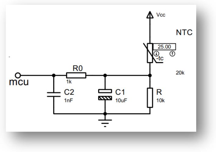
In figure the NTC sensor is series with resistor R. According to voltage divider rules the output voltage
Vout = (R/( Rntc + R)) x Vin , where Vin = 3.3V & R in Kilo ohm (on board resistor)
Or Rntc = R x 3.3 / Vout – R
Here we use 12bit ADC so Vout is the measure ADC_Value & 3.3V is 4095, So the final result is-
Rntc = R x 4095 / ADC_Value – R,
If on board R is 10k ohm, then Rntc = 10 x 4095/ ADC_Value – 10
#include <math.h>
#define ADC_MAX 4095
volatile float ntc_temp;
volatile uint16_t adc_value;
volatile float resistance;
float ntc_temperature(void)
  {
    float cal;
    resistance=(float)ADC_MAX/adc_value;
    resistance=(10*resistance)-10;          // value of on board resistor is 10k
    cal=log(resistance/5);
    ntc_temp=(cal/3950)+(1/298.15);
    ntc_temp=1/ntc_temp;                    // In kalvin
    ntc_temp=ntc_temp-273.15;               // In Degree Celsius
    return (float)ntc_temp;
}
Let’s first initialize the ADC with 212 bit resolution, discontinues mode with interrupt enable –
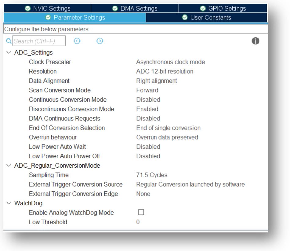
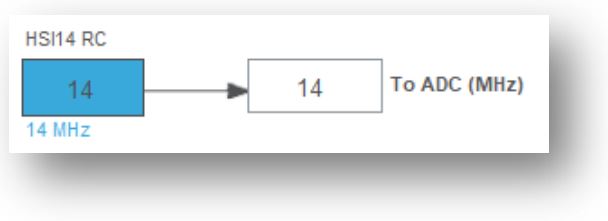
Here ADC use HSI14 RC clock with 14MHz clock frequency. Our logic is very simple, we just call for ADC conversion with interrupt and in ISR (Interrupt Service Routine) we call our main function to get the temperature value.
extern ADC_HandleTypeDef hadc;
void HAL_ADC_ConvCpltCallback(ADC_HandleTypeDef* hadc)
  {
    adc_value=HAL_ADC_GetValue(hadc);
  }
We learn about digital temperature sensor interface with STm microcontroller, we introduce the sensor here for reference check if the NTC give accurate data or not? We use 0.91OLED for display the two temperature data. Please visit my OLED & DS18B20 section for more details. Here is the changed parameter in main program-
#include "ntc.h"
#include "ssd1306.h"
#include "DS18B20.h"
uint8_t temp;
char display_digital[20],display_analog[20];
volatile double f_ntc_temp;
init_OLED();
clear_display();
HAL_ADC_Start_IT(&hadc);
OLCD_write_string(0,0,"IoT ThingHuB ");
while (1)
  {
	f_ntc_temp=ntc_temperature();
    temp=DS18B20ReadTemp();
    HAL_Delay(2000);
    sprintf(display_digital,"Dig:%.4f C ",temperature);
    sprintf(display_analog,"NTC:%.4f C  ",ntc_temp);
    OLCD_write_string(2,0,display_digital);
    OLCD_write_string(4,0,display_analog);
    HAL_ADC_Start_IT(&hadc);
    HAL_Delay(2000);
}
Video describe the full details about initialization and procedure. Here we use ADC channel1 > for NTC value measurement, PB5 > for DS18B20 & I2C1 for 0.9 ” OLED. Here I used breadboard so some tolerance in temperature measurement.


 IoTthingHuB


 Visit Today : 58
 Total Visit : 41174