
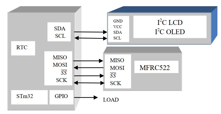
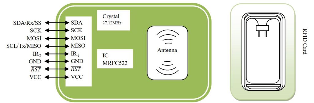
Some time we need a square door lock or square entry for security reasons. RFID card has a unique ID with 1Kb ram. We can write or read from the memory block. The MFRC522 is a highly integrated reader/writer IC for contactless communication at 13.56MHz. Since on board we have 27.12MHz frequency, we have to divide the clock. The MFRC522 can operate in SPI, I2C or UART protocol. In this article we will develop a conference entry with RFID card. In this tutorial we use ST microcontroller with its internal RTC (Real Time Clock) function. You can introduce GSM technology for soft remainder since it has internal calendar with alarm feature. To know more about RFID card reader please goes through my RFID Card Interference section. In Atmel section we learn about SPI communication, the same function works on STM32. Here some useful HAL library for SPI interface as follow-
HAL_SPI_Transmit/ HAL_SPI_Transmit_IT/ HAL_SPI_Transmit_DMA (SPI_HandleTypeDef *hspi, uint8_t *pData, uint16_t Size, uint32_t Timeout);
HAL_SPI_Receive/ HAL_SPI_Receive_IT / HAL_SPI_Receive_DMA (SPI_HandleTypeDef *hspi, uint8_t *pData, uint16_t Size, uint32_t Timeout);
HAL_SPI_TransmitReceive/ HAL_SPI_TransmitReceive_IT / HAL_SPI_TransmitReceive_DMA (SPI_HandleTypeDef *hspi, uint8_t *pTxData, uint8_t *pRxData, uint16_t Size, uint32_t Timeout);
if we use IT no Timeout parameter is needed.
It has also Interrupt function like i.e. HAL_SPI_TxCpltCallback(&hspi), HAL_SPI_RxCpltCallback(&hspi) etc.
In my ATmel section we learn the basic interfacing with RFID. Let’s start your journey with the basic of RFID interface, before start first goes through the datasheet of MFRC522 IC. For SPI communication the 7th bit represent read/write & 0th bit is always 0. So whenever we want to read keep the 7th bit 1, reaming 6 bit will be the address of the register and 0th bit will 0. Similarly for writing purpose, changes in the 7th bit only. The MFRC522 card reader has 7bit unique address to operate as follow-

Let’s build our read & write function using STM32F103RCT6 IC with spi2 & GPIOA pin 4 for chip selection
#define CS_SELECT                 HAL_GPIO_WritePin(GPIOA,GPIO_PIN_4,GPIO_PIN_RESET)
#define CS_DESELECT               HAL_GPIO_WritePin(GPIOA,GPIO_PIN_4,GPIO_PIN_SET)
uint8_t readFromRegister(uint8_t addr)
{
  uint8_t value[2]={((addr<<1)&0x7E)|0x80,0};
  uint8_t Rx_buffer[2];
  CS_SELECT;
  //Read Address format: 1XXXXXX0
  HAL_SPI_TransmitReceive(&hspi2,value,Rx_buffer,2,100);
  CS_DESELECT;
  return Rx_buffer[1];
}
void writeToRegister(uint8_t addr, uint8_t val)
{
  CS_SELECT;
  uint8_t value[2]={(addr<<1)&0x7E,val};
  uint8_t Rx_buffer[2];
  //Write Address format: 0XXXXXX0
  HAL_SPI_TransmitReceive(&hspi2,value,Rx_buffer,2,100);
  CS_DESELECT;
}
For example to reset the MFRC522 we have to send command 0x0F to register Command register: 0x01
void reset(void)
{
  writeToRegister(CommandReg, MFRC522_SOFTRESET); // MFRC522_SOFTRESET: 0x0F
}
To know all the register please goes though the datasheet of MFRC522. Let’s make another 2 function to set & clear the bit of a register.
void setBitMask(uint8_t addr, uint8_t mask)
{
  uint8_t current;
  current = readFromRegister(addr);
  writeToRegister(addr, current | mask);
}
void clearBitMask(uint8_t addr, uint8_t mask)
{
  uint8_t current;
  current = readFromRegister(addr);
  writeToRegister(addr, current & (~mask));
}
Some of our basic functions are done to communicate with MFRC522 card reader. Now our first step is to initialize the MFRC522 card reader. Let’s initialize the MFRC522 with 24ms timer, 100% ASK, CRC value 0x6363 & turn on antenna.
void begin(void)
{
  HAL_GPIO_WritePin(GPIOC,GPIO_PIN_4,GPIO_PIN_SET);
  reset();
  //Timer: TPrescaler*TreloadVal/6.78MHz = 24ms
  writeToRegister(TModeReg, 0x8D);   // Tauto=1; f(Timer) = 6.78MHz/TPreScaler
  writeToRegister(TPrescalerReg, 0x3E);  // TModeReg[3..0] + TPrescalerReg
  writeToRegister(TReloadRegL, 30);  writeToRegister(TReloadRegH, 0);
  writeToRegister(TxAutoReg, 0x40);      // 100%ASK
  writeToRegister(ModeReg, 0x3D);        // CRC initial value 0x6363
  setBitMask(TxControlReg, 0x03);        // Turn antenna on.
}
For reference use https://github.com/Hamid-R-Tanhaei/RFID-MIFARE-RC522-ARM-STM32. When we place a RF card it will return 64bits of data pattern. We just use first 4bits, since the first 4bits are the unique address of the RFID Card. We can also read & write some data to the RF ID card since it has 1kb memory. Let’s start our project with some RFID card reading & note the resultant value to a public name. You can use OLED for display the card number. Here I use debug feature & also I2C OLED for data readout.
uint8_t FoundTag,ReadTag,TagData[16]; // Variable used to store Full Tag Data
FoundTag = requestTag(MF1_REQIDL, TagData);
if (FoundTag == 0x00) ReadTag = antiCollision(TagData);
sprintf(display_tag," %2X,%2X,%2X,%2X ",TagData[0],TagData[1],TagData[2],TagData[3]);
OLCD_write_string(6,0,display_tag);
Here TagData returns 4bits unique address. Assign some name to store the data i.e.
- 0xB3: 0x4A: 0x63: 0xA9 – Subeer Sarkar -> name1
- 0x13: 0xF9: 0xFF: 0xFA – Swarnolata -> name2
Above is the reading data of 2 RFID card. Using those card we just use condition statement to turn ON/OFF a GPIO pin, here I used GPIOA -> Pin8. The basic code as follow-
uint8_t Card1[4]={0xB3,0x4A,0x63,0xA9}; // Subeer Sarkar
uint8_t Card2[4]={0x13,0xF9,0xFF,0xFA}; // Swarnolata
HAL_RTC_GetTime(&hrtc,&sTime,RTC_FORMAT_BCD);
HAL_RTC_GetDate(&hrtc,&sDate,RTC_FORMAT_BCD);
sprintf(display_time," %02X:%02X:%02X ",sTime.Hours,sTime.Minutes,sTime.Seconds);
OLCD_write_string(3,0,display_time);
sprintf(display_time," %02X/%02X/%02X %s",sDate.Date,sDate.Month,sDate.Year,day_name[sDate.WeekDay+1]);
	  OLCD_write_string(4,0,display_time);
if((Card1[0]==TagData[0])&&(Card1[1]==TagData[1])&&(Card1[2]==TagData[2])&&(Card1[3]==TagData[3]))
	 {
		 OLCD_write_string(5,0,"Subeer Sarkar");            // person name here
         OLCD_write_string(6,0,display_time);
		 HAL_GPIO_WritePin(GPIOA, GPIO_PIN_8, GPIO_PIN_RESET);  // open for 10s
		 HAL_Delay(10000);
		 HAL_GPIO_WritePin(GPIOA, GPIO_PIN_8, GPIO_PIN_SET);
		 OLCD_write_string(5,0,"               ");
         OLCD_write_string(6,0,"               ");
	     }
else if((Card2[0]==TagData[0])&&(Card2[1]==TagData[1])&&(Card2[2]==TagData[2])&&(Card2[3]==TagData[3]))
     {
		 OLCD_write_string(5,0,"Swarnolata   ");            // person name here
         OLCD_write_string(6,0,display_time);
		 HAL_GPIO_WritePin(GPIOA, GPIO_PIN_8, GPIO_PIN_RESET);  // open for 10s
		 HAL_Delay(10000);
		 HAL_GPIO_WritePin(GPIOA, GPIO_PIN_8, GPIO_PIN_SET);
		 OLCD_write_string(5,0,"               ");
         OLCD_write_string(6,0,"               ");
	 }
You can introduce as many cards as you wanted & add more else if loop. Here I use internal RTC clock. For most squared entry you can introduce GSM SMS system to send the date & time to the selected person for conference. Assume the conference time 6th January 2025 at 10am to 11am & the control logic works according to that time and card only works on that interval, the logic will be –
FoundTag = requestTag(MF1_REQIDL, TagData);
if(sTime.Hours == 0x10 && sDate.Date == 0x06 &&  sDate.Month == 0x01)
if (FoundTag == 0x00) ReadTag = antiCollision(TagData); // Read tag only at 10am, 06/01/25
MFRC522 📱 SPI Interface ▶ RFID Card Reader


 IoTthingHuB


 Visit Today : 58
 Total Visit : 41174