
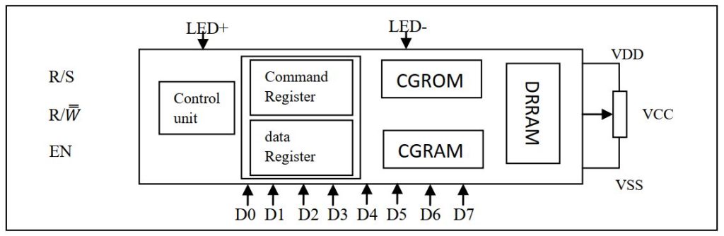
We previously learn about LCD display. In this article we build our own custom character. A standard alphanumeric LCD display has CGRAM area to create user defined patterns. To build a custom pattern we need to write values to the CGRAM area defining which pixel to glow. The values are to be written in the CGRAM address starting from 0x40. The CGRAM has a total of 64bits.
When you are using LCD as 5×8 dots in function set, then you can defined a total of 8 user defined patterns containing 1 byte for each raw and rows for each pattern. When LCD is working in 5×10 dots you can defined 4 user defined pattern. If you are using the cursor than it is recommended not to use the 8th raw.
Let begin our examination by making a ‘tone’ pattern as shown bellow-
Here 1——– Pixel is glowing
0——– pixel is off
The next step is to store the value in DDROM. Let’s build a complete 8 user defined pattern and display it in LCD. Fast thing is you need is to draw the custom character and find the coding.
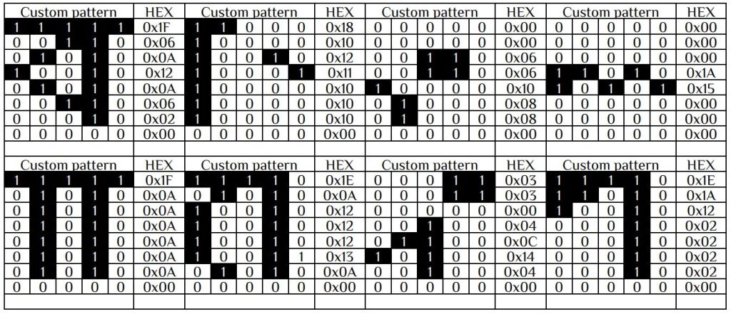
Now our pattern is ready. The next step is to store those values. Let’s store this value in a two dimensional character array.i.e.
unsigned char pattern[8][8]={
{0x1F, 0x06, 0x0A, 0x12, 0x0A, 0x06, 0x02, 0x00},
{0x18, 0x10, 0x12, 0x11, 0x10, 0x10, 0x10, 0x00},
{0x00, 0x00, 0x06, 0x06, 0x10, 0x08, 0x08, 0x00},
{0x00, 0x00, 0x00, 0x1A, 0x15, 0x00, 0x00, 0x00},
{0x1F, 0x0A, 0x0A, 0x0A, 0x0A, 0x1A, 0x0A, 0x00},
{0x1E, 0x0A, 0x12, 0x12, 0x12, 0x13, 0x0A, 0x00},
{0x03, 0x03, 0x00, 0x04, 0x0C, 0x14, 0x04, 0x00},
{0x1E, 0x1A, 0x12, 0x02, 0x02, 0x02, 0x02, 0x00}
};
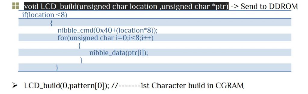
We need to send the bit pattern in proper location in DDROM. Let’s look into the table bellow-

Since the position has an incremental value we have to build one function to store the value in DDROM with start address 0x40.
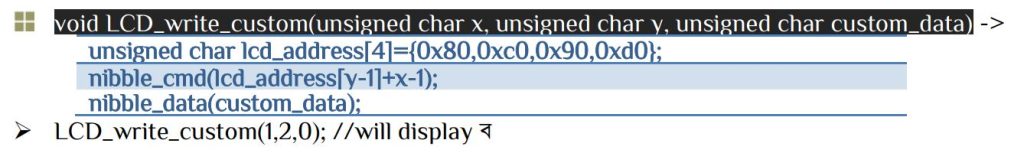
Similarly other pattern can be written in CGRAM. To display the custom character let’s make a function –
LCD driver file[ lcd.c & lcd.h ] contain all the necessary function. To write your own custom character just replace your custom with pattern[8][8] that we already discuss before. The main function-
#include<avr/io.h>
#include<util/delay.h>
#include<stdio.h>
#include"lcd.h"        // PORTD as LCD port
int main(void)
{
LCD_INIT();
LCD_Clear();
while(1)
	{

				LCD_write_string(1,1,"ARM Electronic");
				LCD_write_custom(1,2,0);
				LCD_write_custom(2,2,1);
				LCD_write_custom(3,2,2);
				LCD_write_custom(4,2,3);
				LCD_write_custom(5,2,4);
				LCD_write_custom(6,2,5);
				LCD_write_custom(7,2,6);
				LCD_write_custom(8,2,7);
	}
return 0;
}


 Electronic Real Wrold


 Visit Today : 142
 Total Visit : 34319