
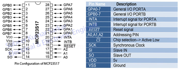
In this article we increase I/O port with the help of IC MCP23S17 which has 16-bit remote bidirectional I/O port with High-speed SPI interface (10 MHz).
Let’s look at the Control register for addressing mode-
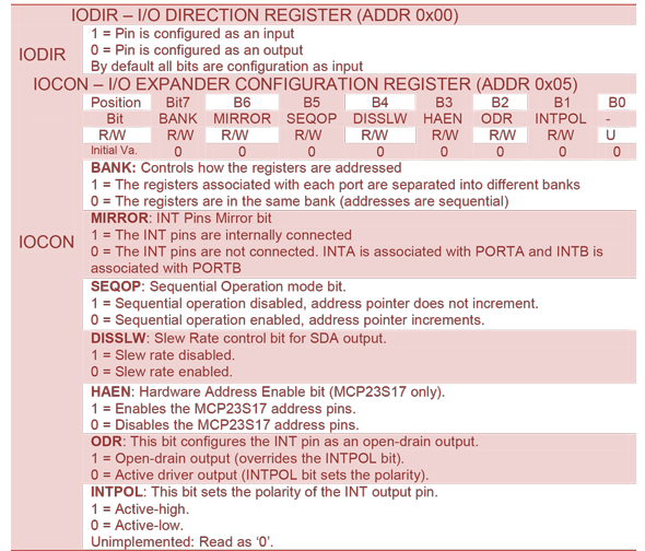
One register (IOCON) is shared between the two ports. The PORTA registers are identical to the PORTB registers, therefore, they will be referred to without differentiating between the port designation (i.e., they will not have the “A” or “B” designator assigned). So you can change either IOCONA or IOCONB.
The MCP23S17 CONTROL REGISTER SUMMARY (IOCON.BANK = 0)
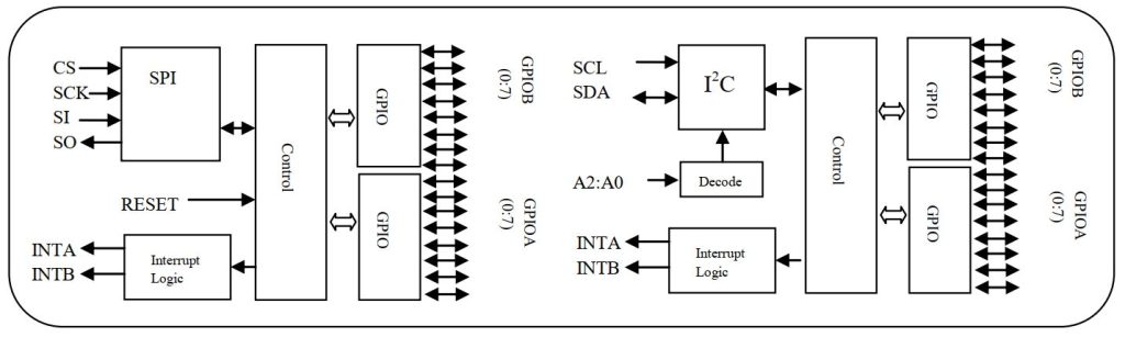
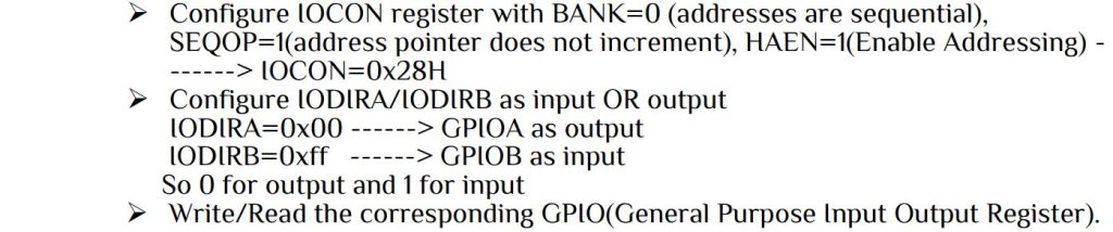
Here MCP23S17 works in SPI interface and MCP23017 works on I2C interface. The necessary steps of configuration as I/O PORT is-
Let’s look at the SPI protocol for this IC
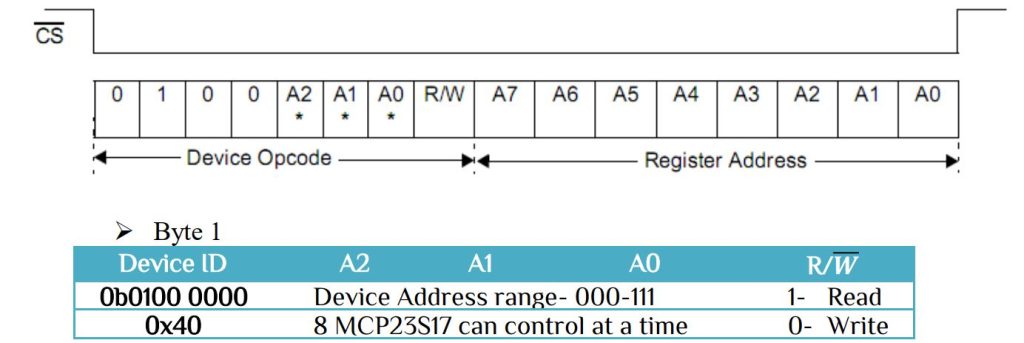
Thus for Read/Write operation
Read —–>SPDR=ID|(ADDRESS<<1)|READ
Write —–>SPDR=ID|(ADDRESS<<1)|WRITE
- Byte 2
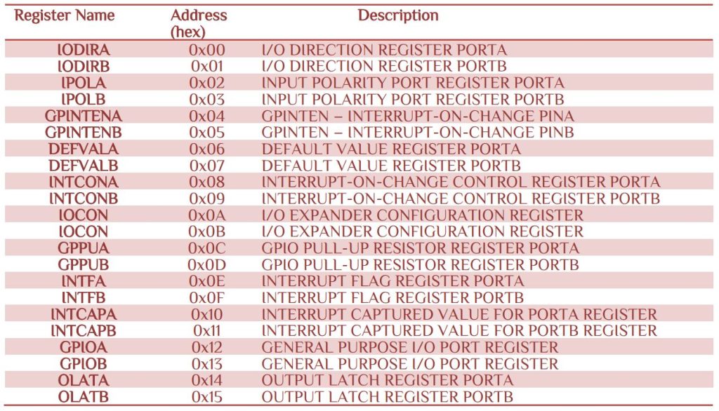
Register Address – Select the desire register from IOCON.BANK = 0 table.
Write Operation
For write operation we need three steps. First we send Byte 1 that content Device ID, Address and Read operation. Then we send the Register address and after that we send register data. The control code for write operation as follow-
- void SPIWrite(uint8_t add,uint8_t data) -> Write data to the register
#define SPI_SLAVE_ID	0x40
#define SPI_SLAVE_ADD	0x00
#define SPI_SLAVE_WRITE	0x00
void SPIWrite(uint8_t add,uint8_t data)
{
SPI_PORT &= ~(1<<SPI_CS);//slave activated
//initilaze salve device
SPDR=SPI_SLAVE_ID|(SPI_SLAVE_ADD<<1)|SPI_SLAVE_WRITE;
while(!(SPSR&(1<<SPIF)));
SPDR=add;
while(!(SPSR&(1<<SPIF)));
SPDR=data;
while(!(SPSR&(1<<SPIF)));
SPI_PORT |= (1<<SPI_CS);//slave deactivate
}
i.e. SPIWrite(IOCONA,0x28); // I/O Control Register: BANK=0, SEQOP=1, HAEN=1
Read Operation
For read operation the first and second steps are identical. It is interesting that the MCP23S17 does not return any value until we write some value to it. The value should be any value.
uint8_t SPIRead(uint8_t add)
{
SPI_PORT &= ~(1<<SPI_CS);//slave activated
//initilaze salve device
SPDR=SPI_SLAVE_ID|(SPI_SLAVE_ADD<<1)|SPI_SLAVE_READ;
while(!(SPSR&(1<<SPIF)));
SPDR=add;
while(!(SPSR&(1<<SPIF)));
// Send Dummy transmission for reading the data
SPDR = 0x00;
// Wait for transmission complete
while(!(SPSR&(1<<SPIF)));
SPI_PORT |= (1<<SPI_CS);//slave deactivate
return (SPDR);
}
i.e. PORTD=SPIRead(GPIOB); // PORTD is equal to GPIOB of MCP23S17
Let’s make a program in which we use GPB Port as input with internal pull register active and GPA as output. In this program GPA bits are set from up to down and if GPB2 pin press then down to up. Download the spi.c and spi.h files. The man program as follow-
/***************************************************************/
/***************************************************************/
/********      Subeer Kumar Sarkar                **************/
/********      Electrical & Electronic Engineer   **************/
/***************************************************************/
/***************************************************************/
#include<avr/io.h>
#include<util/delay.h>
#include"spi.h"
int main(void)
{
SPIInit();
uint8_t pushButton,shift=1;
/******************** initialize MCP23S17 *******************/
// I/O Control Register: BANK=0, SEQOP=1, HAEN=1(Enable Addressing)
SPIWrite(IOCONA,0x28);
SPIWrite(IODIRA,0x00); //GPIOA as output
SPIWrite(IODIRB,0xff); //GPIOB as input
SPIWrite(GPPUB,0xff);  //enable pull-up resister for GPB
_delay_ms(5);
/*************************************************************/
while(1)
{
	pushButton=SPIRead(GPIOB);
	if(pushButton == 0b11111011)
	{
		for(int i=7;i>=0;i--)
		{
			SPIWrite(GPIOA,(1<<i));
			_delay_ms(50);
		}
	}
	else
		SPIWrite(GPIOA,shift);
		_delay_ms(50);
		shift=(shift<<1);
		if(shift == 0)
		shift=1;
	}
return 0;
}


 Electronic Real Wrold


 Visit Today : 136
 Total Visit : 34313