
The TFT module is a 128*160 matrix, controlled by the onboard Sitronix ST7735 controller IC. It is a low cost faxable LCD module. TFT stands for Thin Flim Transistor which is a display screen technique used in LCD (liquid crystal display). An active component that serves as a switch for each pixel to be switched on and off is TFT. TFT display has color and any shape and design can be display. We need proper controlling SPI communication to display in TFT. First let’s look the connection diagram.
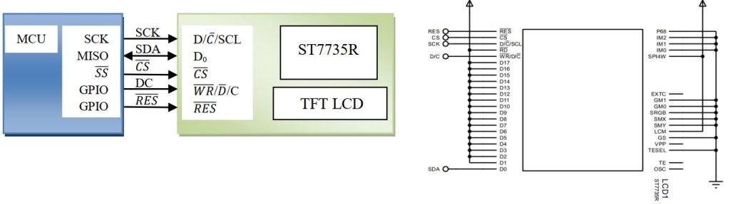
Don’t worry about the internal connection; it’s already connected into the module available. Look at the pin available in the driver
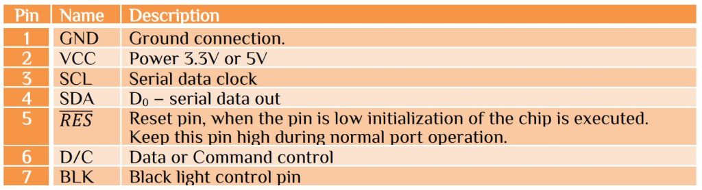
The module has both hardware and software reset function. We use software reset control. If you have available pin then used a GPIO pin to pull the reset line low for at least 1ms then set the GPIO pin to high state. After hardware reset or software reset wait at least 150ms then transfer data and command. How we send command or data to the TFT display? It is very simple. Pin6 is D/C function for data and command control. D/C is 1 for data and D/C is 0 for command set. Use SPI initialize with maximum clock cycle with mode0. Here we only transfer data or command so need for return function. Look at the function for transfer data and command.
void WriteCmd (uint8_t cmd) -> Command send
void WriteCmd (uint8_t cmd)
{
 SPI_PORT&=~(1<<SPI_DC_PIN);
 // clear pin B1=DC; 0=command, 1=data
 SPDR = cmd; // initiate transfer
 while(!(SPSR&(1<<SPIF)));
 SPI_PORT|=(1<<SPI_DC_PIN);
 // set pin return DC high
}
void WriteByte (uint8_t b) -> Data send
void WriteByte (uint8_t b)
{
 SPDR = b; // initiate transfer
 while(!(SPSR&(1<<SPIF)));
}
First initialize the TFT LCD. It need some command, here we used software reset.
void InitDisplay(void)
{
     WriteCmd(SWRESET);      // SWRESET  = 0x01
     _delay_ms(1);           // 1mS is enough
     WriteCmd(SWRESET);      // SWRESET  = 0x01
     _delay_ms(150);         // wait 150mS for reset to finish
     WriteCmd(SLPOUT);       // take display out of sleep mode, SLPOUT =  0x11
     _delay_ms(150);         // wait 150mS for TFT driver circuits
     WriteCmd(COLMOD);       // select color mode, COLMOD  = 0x3A
     WriteByte(0x05);        // mode 5 = 16bit pixels (RGB565)
     WriteCmd(DISPON);       // turn display on, DISPON = 0x29
}
Why we send 0x05 command after select color mode? The TFT display has color combination-
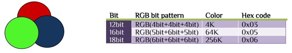
We use 16bit or 2byte format which has Red color 5bit, Green color 6bit and Blue color 5Bit. Example for black 0x0000, blue 0x001F, red 0xF800, green 0x0400 etc. Now if we want to send color to display we have to send the hex value after memory write command.
void Write565 (int data, unsigned int count)
{
WriteCmd(RAMWR); // memory write command, RAMWR = 0x2C
for (;count>0;count--)
	{
      SPDR = data >> 8 ;   // write upper 8 bits
      while(!(SPSR&(1<<SPIF)));
	  SPDR = data & 0xFF;  // write lower 8 bit
      while(!(SPSR&(1<<SPIF)));
	}
}
In LCD just set the coordinate location (x,y) and send data to display, but TFT it is not so simple. Because the coordinates are not a single location, it is a rectangular region. To specify the region we need the controller commands CASET and RESET. The column address set command 0x2A, set the column boundaries or X coordinates. The row address set command 0x2B, set the row boundaries or Y coordinates.
void SetAddrWindow(uint8_t x0, uint8_t y0, uint8_t x1, uint8_t y1)
{
  WriteCmd(CASET); // set column range (x0,x1), CASET = 0x2A
  WriteWord(x0);
  WriteWord(x1);
  WriteCmd(RASET); // set row range (y0,y1), RASET = 0x2B
  WriteWord(y0);
  WriteWord(y1);
}
Since the TFT display is nothing but a set of (128*160) dots pixel. To set any dots at any position is just send coordinates and colors. To set a pixel the function is the combination as follow-
void DrawPixel (uint8_t x, uint8_t y, int color) //Pixel On/Off
{
	SetAddrWindow(x,y,x,y);
	Write565(color,1);
}
With is pixel format we can write line, rectangular, triangle. ellipse or circle. But what about characters? Unlike the 16×2 LCD character display modules, we can’t send its ASCII code 0x39 and expect to see corresponding ‘9’ is appear on the display. We previously build custom character in LCD display, now we implement previous technique to create ‘9’. We use 6×8 pixel region and draw in 5×7 pixel. So that we have space to display the next digit to the display.
Similarly other character can be draw by pixel mapping. Now if pixel is 0 set the pixel color background, if pixel is 1 set the pixel color to foreground. Calculate every character value and store in flash memory. Let’s display ‘9’ to the display –
const uint8_t FONT_CHARS[9][5] PROGMEM ={
     { 0x3E, 0x51, 0x49, 0x45, 0x3E }, // 0
     { 0x00, 0x42, 0x7F, 0x40, 0x00 }, // 1
     { 0x42, 0x61, 0x51, 0x49, 0x46 }, // 2
     { 0x21, 0x41, 0x45, 0x4B, 0x31 }, // 3
     { 0x18, 0x14, 0x12, 0x7F, 0x10 }, // 4
     { 0x27, 0x45, 0x45, 0x45, 0x39 }, // 5
     { 0x3C, 0x4A, 0x49, 0x49, 0x30 }, // 6
     { 0x01, 0x71, 0x09, 0x05, 0x03 }, // 7
     { 0x36, 0x49, 0x49, 0x49, 0x36 }, // 8
     { 0x06, 0x49, 0x49, 0x29, 0x1E }, // 9
}
void PutCh (char ch, uint8_t x, uint8_t y, int color)
{
  int pixel;
  uint8_t row, col, bit, data, mask = 0x01;
  SetAddrWindow(x,y,x+4,y+6);
  WriteCmd(RAMWR);
  for (row=0; row<7;row++)
      {
      for (col=0; col<5;col++)
           {
             data = pgm_read_byte(&(FONT_CHARS[ch][col]));
             bit = data & mask;
             if (bit==0) pixel=BLACK;
             else pixel=color;
             WriteWord(pixel);
           } mask <<= 1;
      }
}
Similarly other character can be writing into the TFT. One interesting thing is that you can rotate the screen. The TFT display can be orientated in any direction. Before going into programming fist clear all the display, it is simply by sending 0 to the pixel. Then orientate the screen. The 2 functions are.
void ClearScreen(void)
{
  SetAddrWindow(0,0,XMAX,YMAX); // set window to entire display
  WriteCmd(RAMWR);              // memory write command, RAMWR = 0x2C
  for (unsigned int i=40960;i>0;--i) // byte count = 128*160*2
	{
	   SPDR = 0 ;
       while(!(SPSR&(1<<SPIF)));
	}
}
void SetOrientation(int degrees)
{
  uint8_t arg;
  switch (degrees)
	{
	case 90: arg = 0x60; break;
	case 180: arg = 0xC0; break;
	case 270: arg = 0xA0; break;
	default: arg = 0x00; break;
	}
  WriteCmd(MADCTL); //axis control, MADCTL = 0x36
  WriteByte(arg);
}
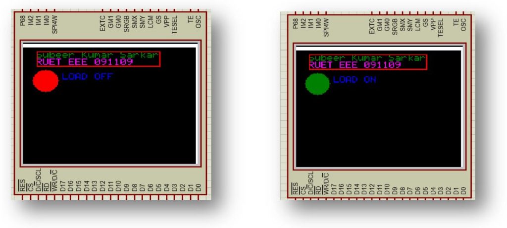
Here we write a program is to display load condition. We use pin PB7 for load. If PB7 is 1 display shows LOAD ON and circle turn green. If PB7 is 0 display shows LOAD OFF and circle turn green. The main program as follow-
/***************************************************************/
/********      Subeer Kumar Sarkar                    **********/
/********      Electrical & Electronic Engineer       **********/
/***************************************************************/
/********   Program for ghraphical display interface  **********/
/***************************************************************/
/***************************************************************/
  #include<avr/io.h>
  #include<util/delay.h>
  #include"TFTLCD.h"
  int main(void)
  {
    init_spi();    //Initilize SPI
    InitDisplay(); // initialize TFT controller
    _delay_ms(500);
    ClearScreen();
    SetOrientation(90);// value should 90,180,270
    DDRB|=(1<<DDB7);   //For load
    char *str = "Subeer Kumar Sarkar"; // text to display
    GotoXY(2,1); // position text cursor
    WriteString(str,GREEN); // display text
    char *ptr = "RUET EEE 091109"; // text to display
    WriteStringXY(2,2,ptr,MAGENTA); // display text
    DrawRect(12,8,126,24,RED);
    while(1)
	   {
		PORTB|=(1<<PB7);
		FillCircle(20,40,12,GREEN);
		WriteStringXY(6,4,"LOAD ON ",BLUE); // display text
		_delay_ms(3000);
		PORTB&=~(1<<PB7);
		FillCircle(20,40,12,RED);
		WriteStringXY(6,4,"LOAD OFF",BLUE); // display text
		_delay_ms(3000);
	}
 return 0;
}


 Electronic Real Wrold


 Visit Today : 136
 Total Visit : 34313