
ARM stands for Advanced RISC Machines. ARM is a family of RISC instruction set architectures (ISAs) for computer processors. Due to their low costs, low power consumption, and low heat generation, ARM processors are useful for light, portable, battery-powered devices, including Smartphone’s, laptops, and tablet computers, as well as embedded systems. However, ARM processors are also used for desktops and servers, including the world’s fastest supercomputer (Fugaku) from 2020 to 2022. ARM is the most widely used family of instruction set architectures. We learn about the STM32 arm processor released by STMicroelectronics. The STM32 is a family of microcontroller ICs based on various 32-bit RISC ARM Cortex-M cores. The STM32 medium-density performance line family incorporates the high-performance Arm® Cortex®-M3 32-bit RISC core operating at a 24 to 480 MHz frequency, high-speed embedded memories, and an extensive range of enhanced I/Os and peripherals connected to APB buses. All devices offer two 12-bit ADCs, RTC(Real time clock), IRTM(Infrared Interface), IWDG( Independent Watchdog), WWDG( System Window Watchdog), general purpose 16-bit timers, PWM timer, as well as standard and advanced communication interfaces:I2Cs and SPIs, USARTs, USB, CAN, Touch Sensor etc. There are many IDE( Integrated Development Environments) for programming STM32 microcontroller some are-
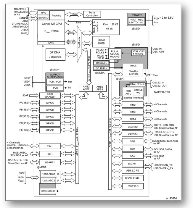
Let’s look at the internal structure of a STM32F103xx
Unlike in AVR the clock section we only have one clock to operate all peripherals i.e. GPIO, SPI, URAT etc, but in STM32 the different clock perform different function. For example GPIO, Timer1, SPI1 operate on APB2 clock and Timer2, SPI2 operate on APB1 clock source, RTC works on internal 40kHz or external clock. So clock configuration is a very important function in STM32.One very interesting fact that in AVR tutorials we learn to create the basic controlling function create by our own bit setting but in STM32 IDE’s there are build in feature and function. We just have to operate the function in proper order. We configure our peripherals in STM32CubeMX and develop the main program in either EWARM/Keil/STMcube.
GPIO: Each I/O port bit is freely programmable. The general-purpose I/O (GPIO) ports can be individually configured by software in several modes:
- Input floating : Default configuration in input setting
- Input pull-up: In input mode the GPIO pin can be configure as pull-up. So the default pin value is 1 and pin works on 0 or GND.
- Input-pull-down: In input mode the GPIO pin can be configure as pull-down. So the default pin value is 0 and pin works on 1 or VCC.
- Analog
- Output open-drain/ push-pull with pull-up or pull-down capability
- Alternate function open-drain/push-pull with pull-up or pull-down capability
In output mode the GPIO pin speed can be configure as Low speed/Medium speed/High speed. We configure the GPIO in HAL library generated by STM32CubeMX. All libraries are already built in HAL library; we have to just use it in different section. HAL library for GPIO are-
HAL_GPIO_ReadPin(GPIOx, GPIO_Pin) -> Read Input Status
HAL_GPIO_WritePin(GPIOx, GPIO_Pin, PinState) -> Set high or low
HAL_GPIO_TogglePin(GPIOx, GPIO_Pin) -> Toggle the Output pin
HAL_GPIO_LockPin(GPIOx, GPIO_Pin) -> Lock the Pin
Here > x can be (A..F), GPIO_PIN_x > x is number
PinState: GPIO_PIN_SET or 1 & GPIO_PIN_RESET or 0.
Each GPIO pin can be configured as External Interrupt Request.
HAL_GPIO_EXTI_IRQHandler(uint16_t GPIO_Pin) or void HAL_GPIO_EXTI_Callback(uint16_t GPIO_Pin)
Let’s first build our main program with toggle a pin according the input sate of a pin. We also show in debug section how many times the switch has been pressed.
The debug extensions allow the core to be stopped either on a given instruction fetch (breakpoint) or data access (watch point). When stopped, the core’s internal state and the system’s external state may be examined. Once examination is complete, the core and the system may be restored and program execution resumed. Please follow the video part for our first program with STM32 microcontroller. In this example we use STM32F0308-DISCO board.
Functions: Configure PA0 pin as input with pull-down and PC8 as output pin.
uint8_t press;
if(HAL_GPIO_ReadPin(GPIOA,GPIO_PIN_0))
		{
		 HAL_GPIO_TogglePin(GPIOC, GPIO_PIN_8);
			HAL_Delay(200);//200ms delay
			press++;
		}
Here we introduce a function HAL_Delay(value);-> delay function in milliseconds. For microseconds delay we need timer in that case, there is no inbuilt delay function for microseconds. For the basic of Timer, ADC, SPI, I2C & UART please go through all the section describe in Atmel part. In Arm section we will cover the entire topic in different examples/interface.
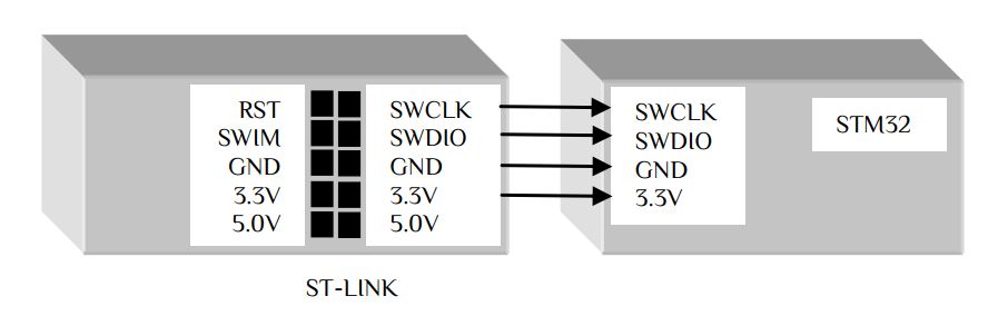
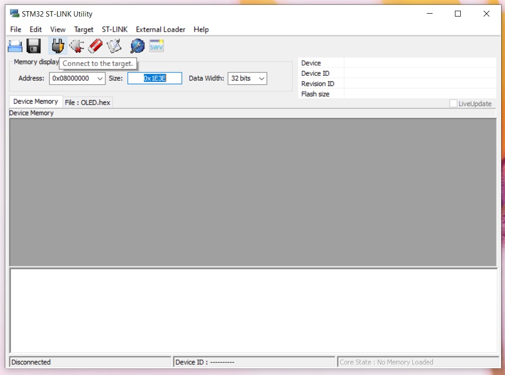
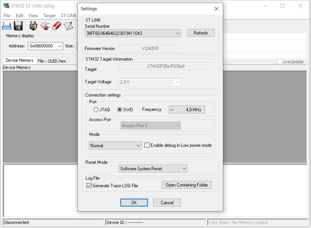
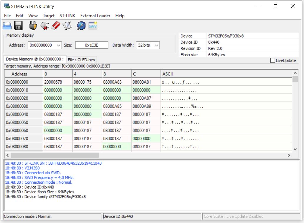
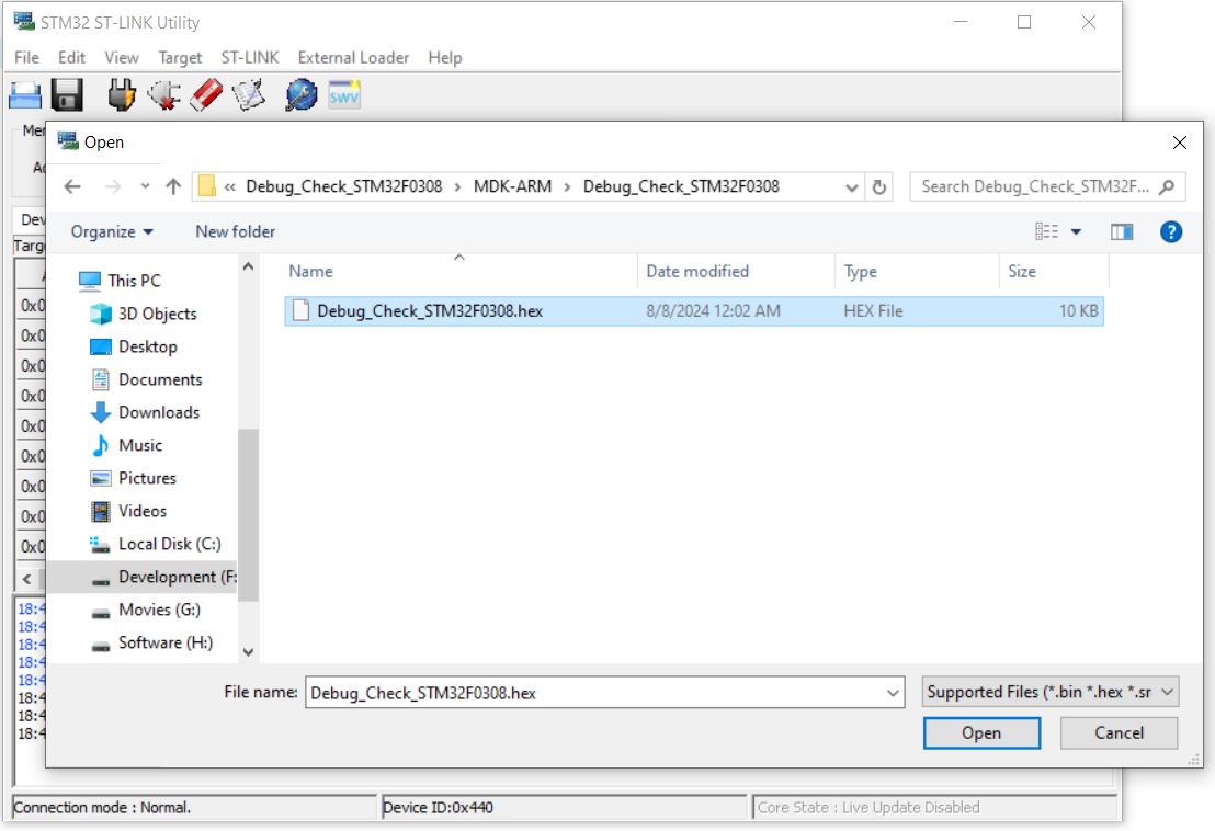
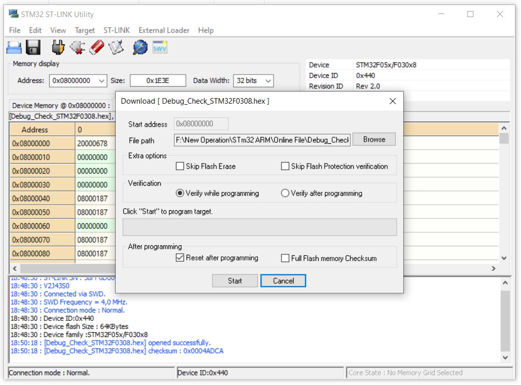
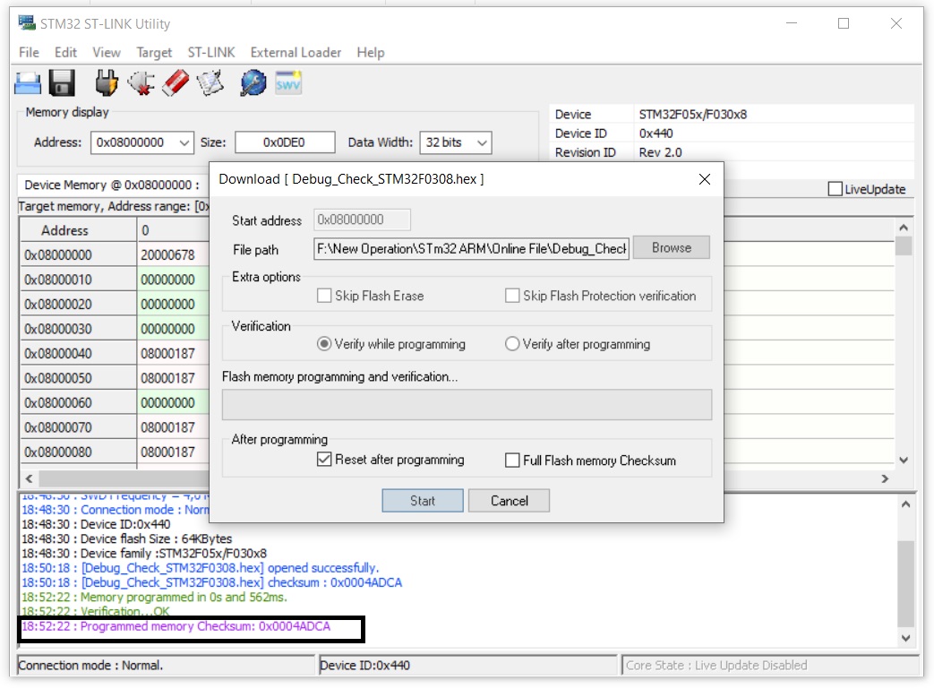
In this example Keil generate a .hex file Project Name>MDK-ARM>Project Name .hex as same as in Atmel Part. We have to load the flash either in-
- STM32 ST-LINK Utility or Keil


 Electronic Real Wrold


 Visit Today : 132
 Total Visit : 34309