
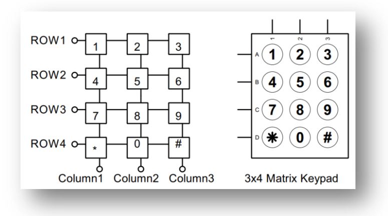
We previously interface Keypad with Atmel microcontroller. Now we will interface keypad with STm32. We will interface STm32 with 3×4 matrix keypad. 4 rows which will be output pins and 3 columns which will be input with pull-up enable.
Since the input pins are pull-up enable the default value is 1 and active with logic 0 to the pin. So our first step is to sequentially set & reset the rows. We will reset(0) one row at a time and other rows will be set(1). For example if we press 1 then row1 will be zero and column1 will get a value of 0. So our logic is whenever a switch will press the corresponding row and column will zero. Since there are 4 rows we will create a loop of 4 and read the input.
If we define each rows and column with a value then we will easily get the code. Since each row and column has a unique value we easily find out which switch is pressed. For example if we define row1 as 0x08 and column1 as 0x08, then if 1 is pressed the code will be 0x88. Here we use any GPIO pins and we predefine some value. That will help you to changed GPIO according to your desire GPIO. For example we use following pins and row & column as-

#define ROW1_RESET   HAL_GPIO_WritePin(GPIOA,GPIO_PIN_6,GPIO_PIN_RESET)
#define ROW1_SET     HAL_GPIO_WritePin(GPIOA,GPIO_PIN_6,GPIO_PIN_SET)
#define ROW2_RESET   HAL_GPIO_WritePin(GPIOA,GPIO_PIN_7,GPIO_PIN_RESET)
#define ROW2_SET     HAL_GPIO_WritePin(GPIOA,GPIO_PIN_7,GPIO_PIN_SET)
#define ROW3_RESET   HAL_GPIO_WritePin(GPIOC,GPIO_PIN_4,GPIO_PIN_RESET)
#define ROW3_SET     HAL_GPIO_WritePin(GPIOC,GPIO_PIN_4,GPIO_PIN_SET)
#define ROW4_RESET   HAL_GPIO_WritePin(GPIOC,GPIO_PIN_5,GPIO_PIN_RESET)
#define ROW4_SET     HAL_GPIO_WritePin(GPIOC,GPIO_PIN_5,GPIO_PIN_SET)
#define COLUMN1      HAL_GPIO_ReadPin(GPIOB,GPIO_PIN_0)
#define COLUMN2      HAL_GPIO_ReadPin(GPIOB,GPIO_PIN_1)
#define COLUMN3      HAL_GPIO_ReadPin(GPIOB,GPIO_PIN_2)
In the define section change the pin according to yours desire GPIO. Now the main logic as follow-
unsigned char keycode,keyPressed='\0',i;
uint8_t row,column,column1,column2,column3;
for(i=0;i<4;i++)
	{ HAL_Delay(1);
	if(i==0){
		ROW1_RESET; ROW2_SET; ROW3_SET; ROW4_SET;
				row=0x08;
			}
	else if(i==1){
		ROW1_SET; ROW2_RESET; ROW3_SET; ROW4_SET;
				row=0x04;
			}
	else if(i==2){
		ROW1_SET; ROW2_SET; ROW3_RESET; ROW4_SET;
				row=0x02;
			}
	else if(i==3){
		ROW1_SET; ROW2_SET; ROW3_SET; ROW4_RESET;
				row=0x01;
			}
	HAL_Delay(1);
	if(COLUMN1) column1=0; else column1=0x80;
	if(COLUMN2) column2=0; else column2=0x40;
	if(COLUMN3) column3=0; else column3=0x20;
	column=column1|column2|column3;
	HAL_Delay(20);
	if(column != 0x00)
	{ HAL_Delay(20);
	if(column == 0x00) goto OUT;
	keycode=(row&0x0f)|(column&0xf0);
	switch(keycode)
		{
			case (0x88): keyPressed = '1';
				 		 break;
			case (0x48): keyPressed = '2';
				 		 break;
			case (0x28): keyPressed = '3';
			   			 break;
			case (0x84): keyPressed = '4';
				 		 break;
			case (0x44): keyPressed = '5';
				 		 break;
			case (0x24): keyPressed = '6';
				 		 break;
			case (0x82): keyPressed = '7';
				 		 break;
			case (0x42): keyPressed = '8';
				 		 break;
			case (0x22): keyPressed = '9';
				 		 break;
			case (0x81): keyPressed = '*';
				 		 break;
			case (0x41): keyPressed = '0';
				 		 break;
			case (0x21): keyPressed = '#';
				 		 break;
		}
		OUT:;
	}
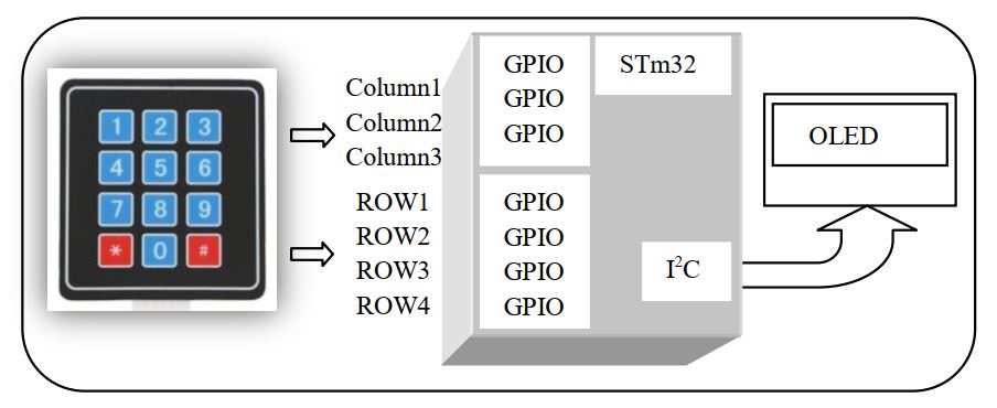
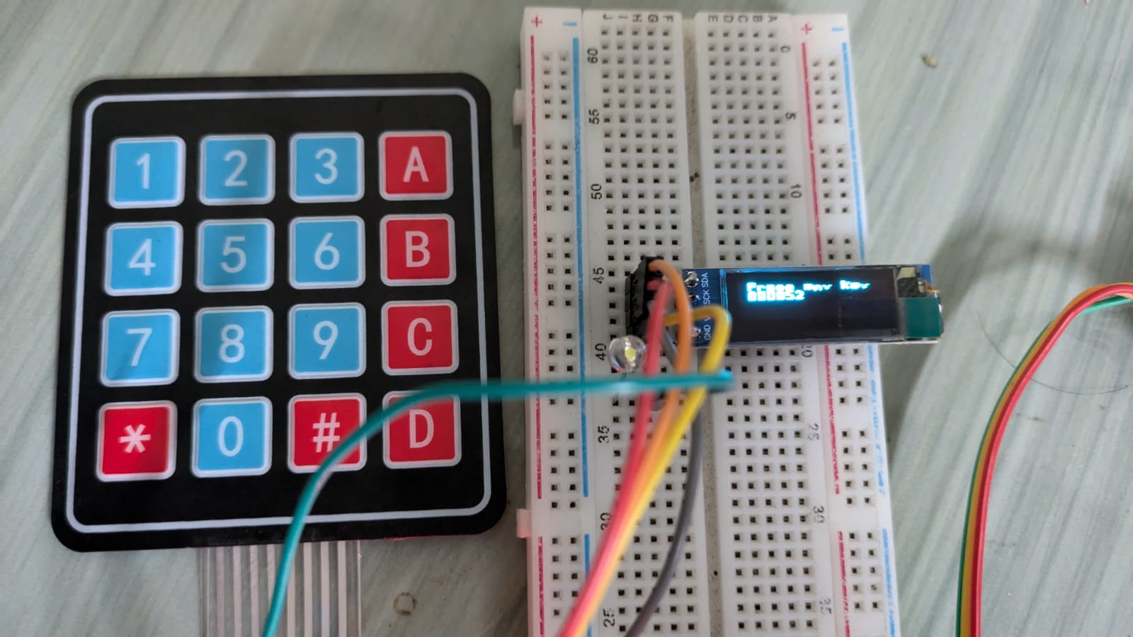
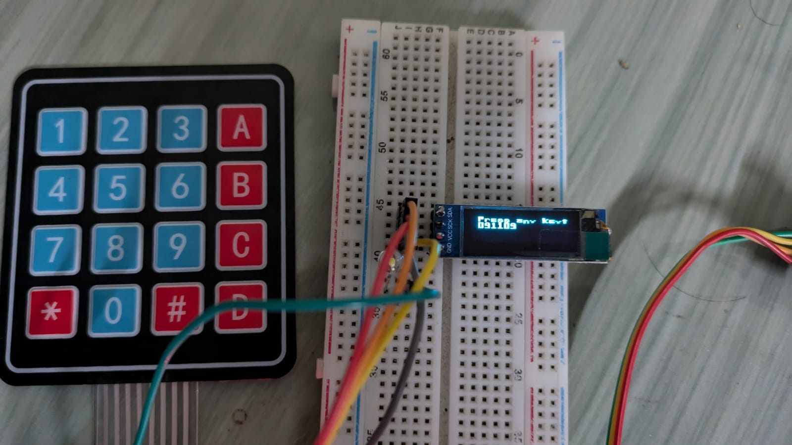
We display the key pressed value in 0.91″ OLED display. Similarly we can use 4×4 matrix keypad with only 1 addition of column4.
3×4 Keypad Connection
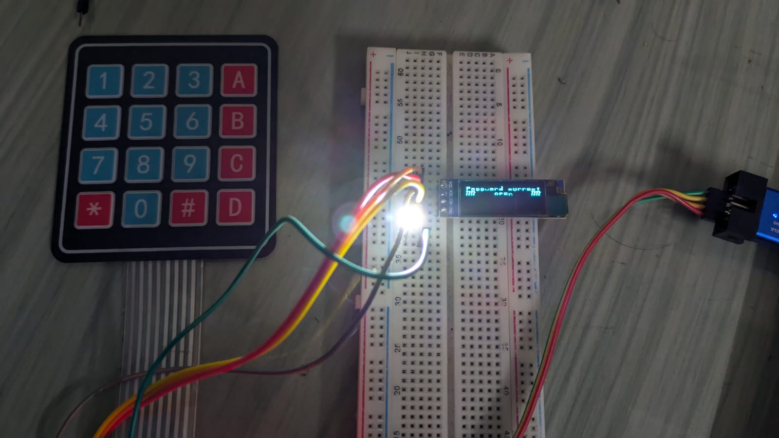
In ATmel microcontroller we developed a password locker with 3×4 matrix keypad. In this section we will make a smart password locker with STM32F103C8Tx with 4×4 matrix keypad. The connection as follow-
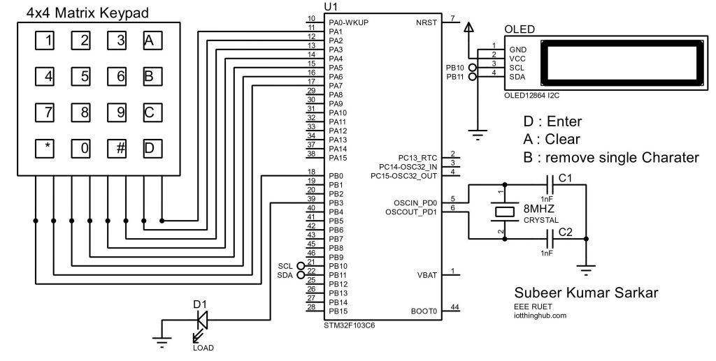

STM32F103C8T6-Blue_Pill is a low cost development board has internal 8MHz crystal. Connect the load in PB3 which is configuring as output. Here 0-9,*,# digits has value and other digits are define as-
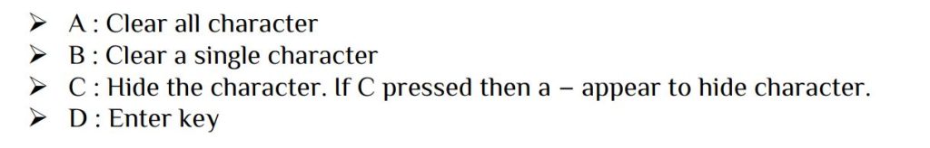
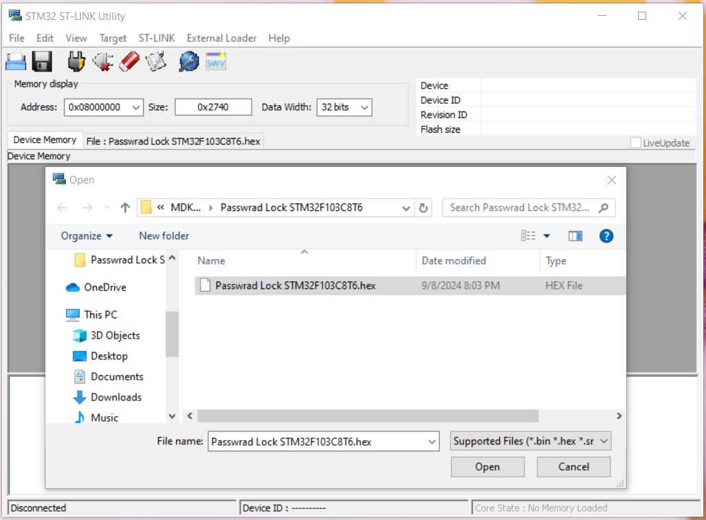
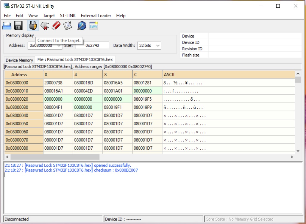
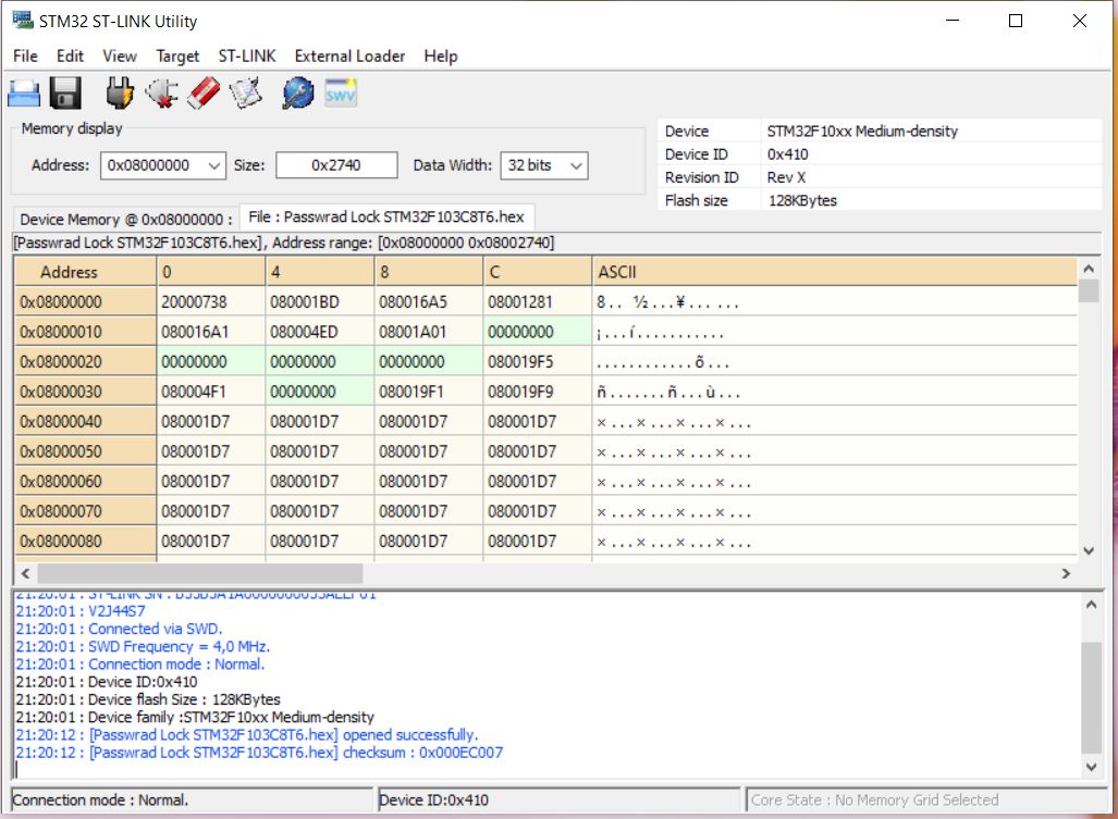
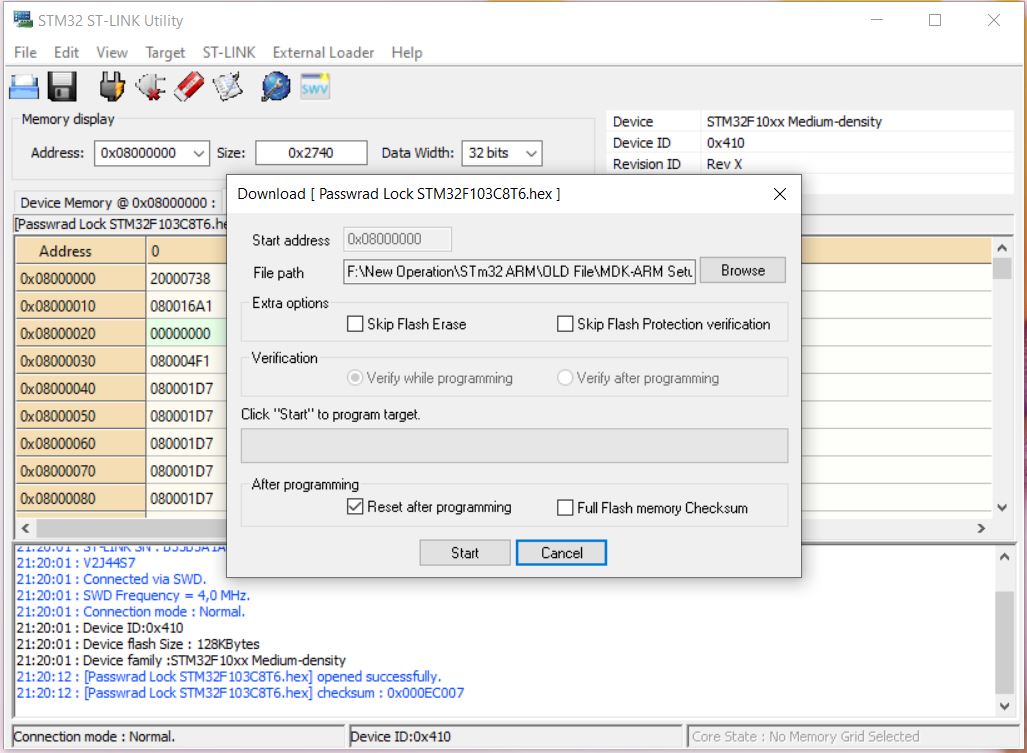
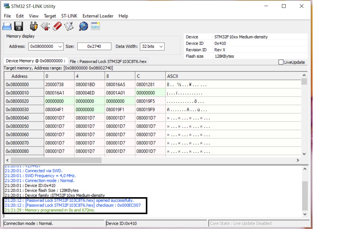
Note: Here ‘D’ key is used for enter. No other external switch has been used. Just download the hex file and burn it in STM32 ST-LINK Utility. For hide key just pressed C key, a – sign indicate it. If you want to see your input character just presses C again.


 Electronic Real Wrold


 Visit Today : 132
 Total Visit : 34309