
In our previous article we use AHT20 sensor which can measure temperature & humidity. But it can’t measure air biometric pressure, so we use another sensor either BME280 or BMP280. Both BMP280 & BME280 can measure biometric pressure & temperature, but BME280 has one extra feature of measuring humidity along with temperature & pressure. In this article we use both AHT20 & BMP280 for weather forecasting, both has I2C interfacing feature. We use OLED in the same I2C bus. Let’s not wasting any time & go to our I2C device BMP280.
BMP280 can operate in 3 different modes, i.e. sleep mode, normal mode & forced mode. The I²C slave BMP280 has 7-bit device address of 111011x. The 6 MSB bits are fixed. The last bit is changeable by SDO value and can be changed during operation. Connecting SDO to GND results in slave address 1110110 (0x76); connection it to VDDIO results in slave address 1110111 (0x77). Let first look at the register mapping & setting according to our requirement.
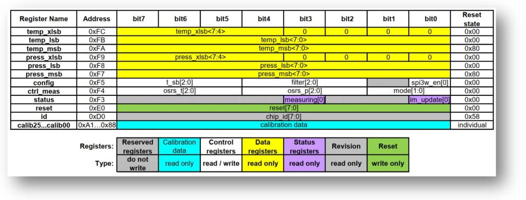
According to the memory map if we first read the register 0xD0 we get the chip id 0x58. Example for soft reset just transmits 0xB6 to the control register 0xE0 we will read out 0x00 as soon as reset done. The HAL Library has lots of I2C function. For making BMP280 library we just use one function-
HAL_I2C_Mem_Read(I2C_HandleTypeDef *hi2c, uint16_t DevAddress, uint16_t MemAddress,uint16_t MemAddSize, uint8_t *pData, uint16_t Size, uint32_t Timeout)
Here,
- DevAddress : 1<<(0x76 or 0x77) = 0xEC or 0xEE
- MemAddress : Internal memory address
- MemAddSize : Size of internal memory address
- pData : Pointer to data buffer
- Size : Amount of data to be sent
- Timeout : Timeout duration
For example to check if the device has connected or not we need to transmit 0xD0 & receive value will be 0x58. The SD0 pin to GND.
#define BME280_ADDRESS 0xEC
uint8_t chipID;
HAL_I2C_Mem_Read(&hi2c1,BME280_ADDRESS,0xD0,1,&chipID,1,1000);
The variable chipID will have the value 0x58, otherwise check the SD0 pin or connection.
For initialization we will only concern with config -> 0xF5, ctrl_meas -> 0xF4 register.
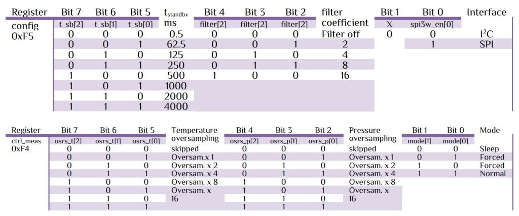
For proper operation the datasheet can provide optimal settings as below-
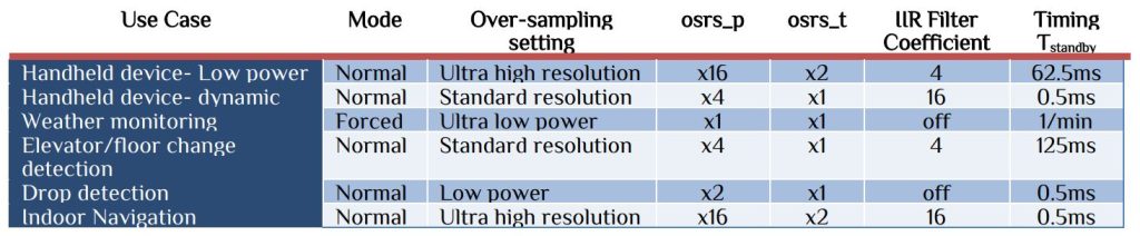
For example to operate in Indoor Navigation mode, the setting will be omode-> normal, ffilter -> filter coefficient 16, Ci2c -> SPI off, tstandby -> 0.5ms, Toversampling -> Oversampling x 2, Poversampling -> Oversampling x 16.
- config Reg 0xF5 -> 0b00010000 or 0x10
- ctrl_meas Reg 0xF4 -> 0b01010111 or 0x57
Next step is to read out Trimming parameter. The trimming parameters are programmed into the devices’ non-volatile memory (NVM) during production and cannot be altered by the customer. Each compensation word is a 16-bit signed or unsigned integer value stored in two’s complement. As the memory is organized into 8-bit words, two words must always be combined in order to represent the compensation word. The 8-bit registers are named calib00…calib25 and are stored at memory addresses 0x88…0xA1. The corresponding compensation words are named dig_T# for temperature compensation related values and dig_P# for pressure compensation related values.
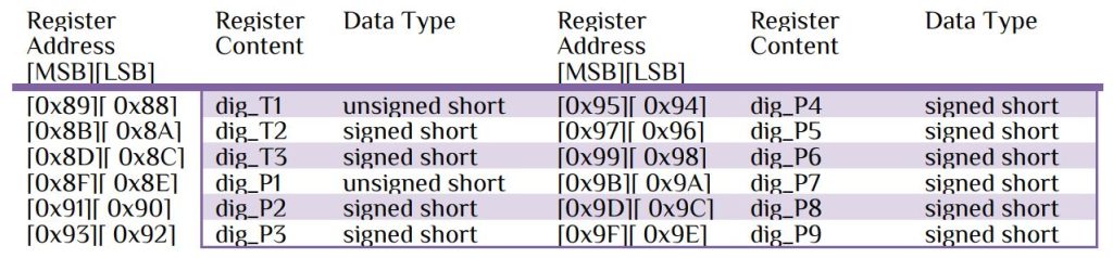
Let’s look at the code for initialization-
#define BME280_ADDRESS 0xEC
uint16_t dig_T1, dig_P1;
int16_t  dig_T2, dig_T3, dig_P2, dig_P3, dig_P4, dig_P5, dig_P6, dig_P7, dig_P8, dig_P9;
void BMP280_init(uint8_t t_sb,uint8_t filter, uint8_t osrs_t, uint8_t osrs_p,uint8_t mode)
{
	uint8_t u8_config,u8_ctrl_meas;
	u8_config=(t_sb<<5)|(filter<<2);
	u8_ctrl_meas=(osrs_t<<5)|(osrs_p<<2)|mode;
	HAL_I2C_Mem_Read(&hi2c1,BME280_ADDRESS,CONFIG_REG,1,&u8_config,1,1000);
	HAL_I2C_Mem_Read(&hi2c1,BME280_ADDRESS,CTRL_MEAS_REG,1,&u8_ctrl_meas,1,1000);
	uint8_t trimming_buff[24];
    HAL_I2C_Mem_Read(&hi2c1,BME280_ADDRESS,TRIMMING_PRA,1,trimming_buff,24,1000);
	dig_T1=(trimming_buff[0])+(trimming_buff[1]<<8);
	dig_T2=(trimming_buff[2])+(trimming_buff[3]<<8);
	dig_T3=(trimming_buff[4])+(trimming_buff[5]<<8);
	dig_P1=(trimming_buff[6])+(trimming_buff[7]<<8);
	dig_P2=(trimming_buff[8])+(trimming_buff[9]<<8);
	dig_P3=(trimming_buff[10])+(trimming_buff[11]<<8);
	dig_P4=(trimming_buff[12])+(trimming_buff[13]<<8);
	dig_P5=(trimming_buff[14])+(trimming_buff[15]<<8);
	dig_P6=(trimming_buff[16])+(trimming_buff[17]<<8);
	dig_P7=(trimming_buff[18])+(trimming_buff[19]<<8);
	dig_P8=(trimming_buff[20])+(trimming_buff[21]<<8);
	dig_P9=(trimming_buff[22])+(trimming_buff[23]<<8);
}
The Trimming parameters are saved in the variables. The “status” register -> 0xF3 contains two bits which indicate the status of the device. Bit3 represents the measuring status & Bit0 represents image register update. After measuring the data will store in the “temp” register. Reading procedure will be from register 0xF7 to 0xFC total 6byte, upper 3byte contents temperature_row value & lower 3byte content pressure_row value.
int32_t temperature_raw, pressure_raw;
uint8_t status, rx_buff[6];
	do
	{
	HAL_I2C_Mem_Read(&hi2c1,BME280_ADDRESS,STATUS_REG,1,&status,1,1000);
	} while(((status&0b00001000)==8)||((status&0b00000001)==1));
    HAL_I2C_Mem_Read(&hi2c1,BME280_ADDRESS,TEMP_REG,1,rx_buff,6,1000);
    temperature_raw=(rx_buff[3]<<12)+(rx_buff[4]<<4)+(rx_buff[5]>>4);
    pressure_raw=(rx_buff[0]<<12)+(rx_buff[1]<<4)+(rx_buff[2]>>4);
For measuring of temperature & pressure the time will be, Total time Ttotal = Tmeasure + Tstandby .
For calculating the API available from Bosch Sensortec to perform readout and compensation. According to the datasheet here we use 32bit calculation-
    float BMP280_Temperature, BMP280_Pressure, BMP280_Altitude;
    double var1, var2;
	var1=(((double)temperature_raw)/16384.0-((double)dig_T1)/1024.0)*((double)dig_T2);
	var2=((((double)temperature_raw)/131072.0-((double)dig_T1)/8192.0)*(((double)temperature_raw)/131072.0-((double)dig_T1)/8192.0))*((double)dig_T3);
	double t_fine = (int32_t)(var1+var2);
    volatile	float T = (var1+var2)/5120.0;
	BMP280_Temperature=T;
	var1=((double)t_fine/2.0)-64000.0;
    var2=var1*var1*((double)dig_P6)/32768.0;
    var2=var2+var1*((double)dig_P5)*2.0;
    var2=(var2/4.0)+(((double)dig_P4)*65536.0);
    var1=(((double)dig_P3)*var1*var1/524288.0+((double)dig_P2)*var1)/524288.0;
    var1=(1.0+var1/32768.0)*((double)dig_P1);
	volatile double p=1048576.0-(double)pressure_raw;
    p=(p-(var2/4096.0))*6250.0/var1;
    var1=((double)dig_P9)*p*p/2147483648.0;
    var2=p*((double)dig_P8)/32768.0;
    p=p+(var1+var2+((double)dig_P7))/16.0;
    BMP280_Pressure=p;
For altitude calculation use barometric function
Altitude, h = 44330 x (1-(P/P0)1/5.255) m, current sea level P0 = 1013.25 millibars
#include "math.h"
BMP280_Altitude=44330.0*(1-pow(BMP280_Pressure/101325.0,1.0/5.255));
For data & time use RTC function, please go to my RTC article for detail. For configuration & output please follow my Youtube video.


 IoTthingHuB


 Visit Today : 58
 Total Visit : 41174