
Bluetooth is a wireless technology used for short-range communication between devices. It operates using radio waves in the 2.4 GHz frequency range and is commonly used for connecting peripherals like headphones, speakers, keyboards, mice, and even smart home devices. There are different versions of Bluetooth, with newer versions (like Bluetooth 5.0, 5.1, and 5.2) offering better range, speed, and power efficiency compared to older versions. There are many devices available for Bluetooth communication, HC05/06 is the most popular one. In this article we use HC05 IC for Bluetooth communication. Let’s start our journey with simple basic commands. Every HC05 module has pin configuration shown in the back side, both Rx & Tx pin can operate in 3.3V, but power supply need 3.6V~6V. Connect Rx pin of HC05 to Tx pin & Tx pin of HC05 to Rx pin of the microcontroller. EN pin is used to select for command or data mode. EN -> 5V enters into command mode & EN->0V enters into normal data mode. By default the device has name HC-05, pin is either 1234 or 0000 & baud rate 38400bits/s.
If any problem entering into AT command mode- Press the push button and re-power the BT module, changes it to continue glow for long time, means we successfully entered at AT command mode. Let’s first see some necessary command & Change some parameter-
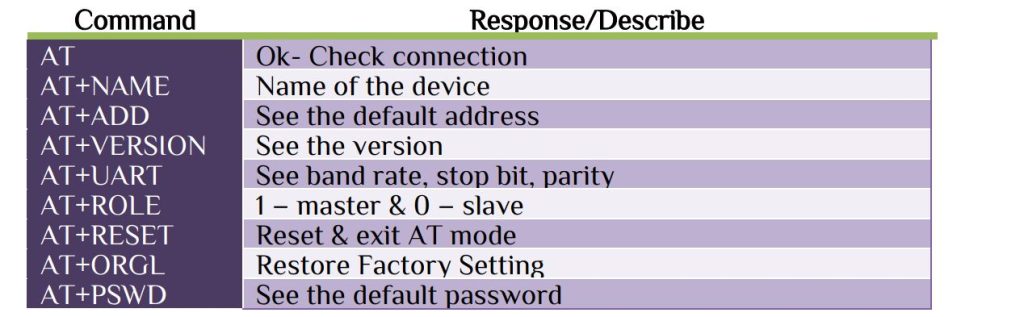
Use any serial terminal software for command, here I use 💻 Realterm software for command. Only 3 parameters which will we set-

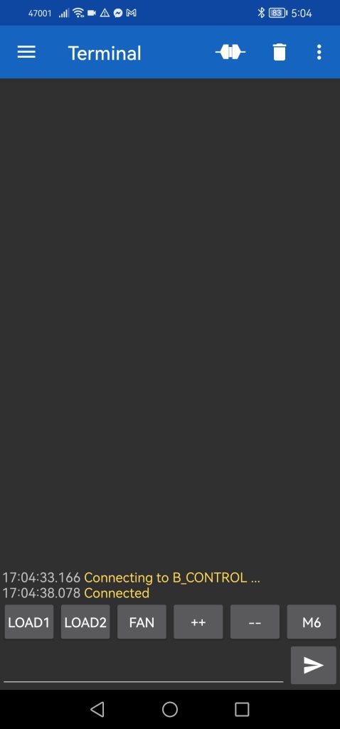
After device configuration, now it is for setting the Bluetooth terminal of mobile. Pair the HC05 with your phone then install 📱 Serial Bluetooth app. The Serial Bluetooth Terminal app can help you to transfer data via Bluetooth. In Serial Bluetooth Terminal -> Devices -> Bluetooth Classic you will find your device. Here we use 2 load with GPIO & 1 load with PWM. 2 GPIO pin will use for simple ON/OFF load & 1 PWM pin will use for pulse control. In this article we use system clock as 48MHz internal clock. For PWM the formula is-
PWM frequency fPWM = fcpu/((1+Prescaler)*(1+ARR))
Let ARR=19999 &Prescaler 47, will generate a frequency of 50Hz. For 50% Duty cycle the CCRx register value will be 9999. Here I use Timer 15 channel 1 for PWM, for 50% Duty cycle-
TIM15->CCR1=9999
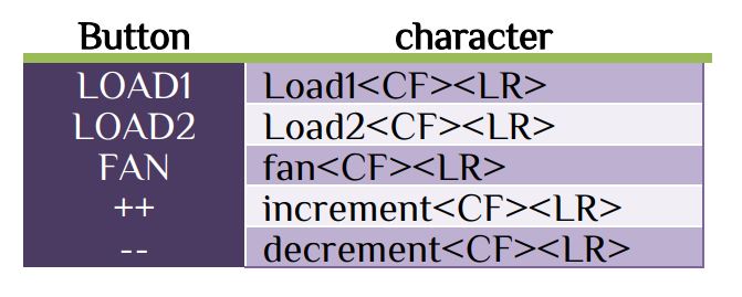
Initialize UART with 9600 baud rate, 1 stop bit & None parity. Here I use UART1 for communicating with Interrupt function. Use ‘\n’ or ‘\r’ as the last received character. The received function-
char display[20];
uint8_t rx_char,i;
extern UART_HandleTypeDef huart1;
void HAL_UART_RxCpltCallback(UART_HandleTypeDef *huart)
{
  if(huart->Instance==USART1 )
  {
    if(rx_char=='\r' || rx_char=='\n')
    i=0;
    else
    display[i++]=rx_char;
    HAL_UART_Receive_IT(&huart1,&rx_char,1);
  }
}
For GPIO control same logic will works on LOAD1 & LOAD2.
if(strstr(display,"load1"))
    {
      HAL_GPIO_TogglePin(GPIOA,GPIO_PIN_0);
      if(HAL_GPIO_ReadPin(GPIOA,GPIO_PIN_0))
      OLCD_write_string(5,1,"LD1 ON ");
      else OLCD_write_string(5,1,"LD1 OFF");
    }
if(strstr(display,"load2"))
    {
      HAL_GPIO_TogglePin(GPIOA,GPIO_PIN_1);
      if(HAL_GPIO_ReadPin(GPIOA,GPIO_PIN_1))
      OLCD_write_string(5,9,"LD2 ON ");
      else OLCD_write_string(5,9,"LD2 OFF");
    }
For PWM on/off we need some modification as follow-
uint8_t b_fan,duty=50;
char fan_display[16];
if(strstr(display,"fan"))
    {
      b_fan=b_fan^0x01;
      if(b_fan)
      {
        HAL_TIM_PWM_Start(&htim15,TIM_CHANNEL_1);
        sprintf(fan_display,"FAN Sp:%i    ",duty);
        OLCD_write_string(6,1,fan_display);
      }else{
        HAL_TIM_PWM_Stop(&htim15,TIM_CHANNEL_1);
        OLCD_write_string(6,1,"FAN OFF        ");
      }
    }
For changing duty cycle we need some modification, here we use different duty cycle.
if(strstr(display,"increment"))
    {
      if(b_fan)
      {
       speed++;
       if(speed>=5)speed=4;
       switch(speed)
       {
       case 0: TIM15->CCR1=4999; //for 25% duty cycle
       OLCD_write_string(6,1,"FAN ON SP:25% ");
       duty=25;
       break;
       case 1: TIM15->CCR1=9999; //for 50% duty cycle
       OLCD_write_string(6,1,"FAN ON SP:50% ");
       duty=50;
       break;
       case 2: TIM15->CCR1=14999;//for 75% duty cycle
       OLCD_write_string(6,1,"FAN ON SP:75% ");
       duty=75;
       break;
       case 3: TIM15->CCR1=17999;//for 90% duty cycle
       OLCD_write_string(6,1,"FAN ON SP:90%  ");
       duty=90;
       break;
	   case 4: TIM15->CCR1=19998;//for 100% duty cycle
       OLCD_write_string(6,1,"FAN ON SP:100%  ");
       duty=100;
       break;
       }
      }
    }
if(strstr(display,"decrement"))
    {
      if(b_fan)
      {
       speed--;
       if(speed<=0)speed=0;
       switch(speed)
       {
       case 0: TIM15->CCR1=4999; //for 25% duty cycle
       OLCD_write_string(6,1,"FAN ON SP:25% ");
       duty=25;
       break;
       case 1: TIM15->CCR1=9999; //for 50% duty cycle
       OLCD_write_string(6,1,"FAN ON SP:50% ");
       duty=50;
       break;
       case 2: TIM15->CCR1=14999;//for 75% duty cycle
       OLCD_write_string(6,1,"FAN ON SP:75% ");
       duty=75;
       break;
       case 3: TIM15->CCR1=17999;//for 90% duty cycle
       OLCD_write_string(6,1,"FAN ON SP:90% ");
       duty=90;
       break;
	   case 4: TIM15->CCR1=19998;//for 100% duty cycle
       OLCD_write_string(6,1,"FAN ON SP:100%  ");
       duty=100;
       break;
       }
      }
	}
Combine those function will be our full program. Now for mobile site change some setting-
For setting please see my Youtube video. Here I use OLED for display purpose. In the video part I use RTC timer to ON/OFF any load at any time&date, but I don’t describe it in this article. Since I only describe the basic part I omitted that. Leave the EN & STATE pin unconnected, since the microcontroller just only read the sting from the mobile terminal.


 IoTthingHuB


 Visit Today : 58
 Total Visit : 41174