
WiFi (Wireless Fidelity) is a technology that allows devices to connect to the internet or communicate with each other wirelessly using radio waves. It operates based on the IEEE 802.11 standard, enabling high-speed data transfer over short distances. The ESP8266 operates exclusively in the 2.4 GHz frequency band. It supports WiFi communication based on the IEEE 802.11 b/g/n standards, which makes it ideal for various IoT applications due to its balance of range and data throughput, as well as its low power consumption. Notably, since it only uses the 2.4 GHz band, it does not support the 5 GHz frequency, which is often used for higher-speed networks in environments with less interference.
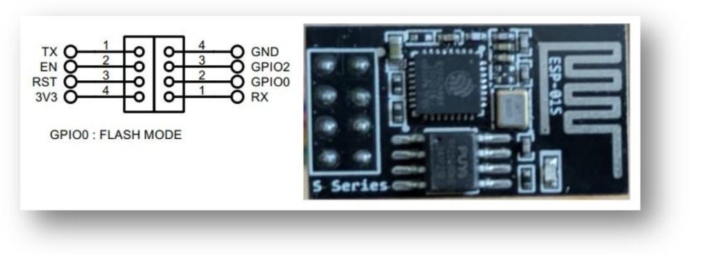
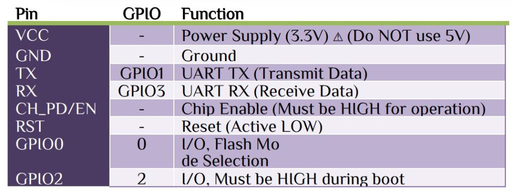
In the previous article we discuss about Bluetooth communication. In HC05 Bluetooth module we initialize it earlier, but in WiFi, esp8266 module we initialize it at run time. In this article we modify our Bluetooth logic with lot’s of changes but the operation will be same. The esp8266 module works on AT command mode. Before starting let’s see some command mode that we need in this article.
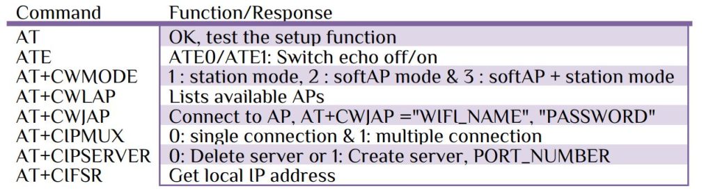
The esp8266 module has many other commands, but in this article we only deal with the above commands. Please see my Youtube video for command set up. At first we send commands through hyper serial terminal. Use any serial terminal software for command; here I use 💻 Realterm software for command. Every commands will send with “\r\n ” at the end. Let’s create a function for sending commands.
char display[140],wifi_send[50],RX_ST[140];
void ESP8266_RX(char *b_send)
{
	sprintf(wifi_send,"%s",b_send);
	HAL_UART_Transmit(&huart1,(uint8_t*)wifi_send,strlen(wifi_send),1000);
	while(1)
	{
		sprintf(RX_ST,"%s",display);
		if(strstr(RX_ST,"OK")) break;
	}
	memset (wifi_send, '\0', 50);  // clear the buffer
	memset (RX_ST, '\0', 140);     // clear the buffer
	count=0;
	HAL_Delay(2000);
}
Here we use character type variable: display to store the RX received data. Every response of esp8266 has a common string of “OK”, so set a break point at “OK” signal. For receiving character we use interrupt call back function.
uint8_t rx_char,count;
void HAL_UART_RxCpltCallback(UART_HandleTypeDef *huart)
{
  if(huart->Instance==USART1 )
  {
    display[count++]=rx_char;
    HAL_UART_Receive_IT(&huart1,&rx_char,1);
  }
}
The call function will become very simple-
ESP8266_RX("AT\r\n");                           // test function
ESP8266_RX("ATE0\r\n");                      // echo off
ESP8266_RX("AT+CWMODE=3\r\n");  // both softAP + station mode
The esp8266 module needs to connect with your WiFi network, i.e. the AT+CWLAP command will show the available networks for esp8266 access point. If it doesn’t show your router name, please enable the 2.4GHz frequency bandwidth. For connecting with router-
char WIFI_NAME[]="WiFi_Name";
char WIFI_PASS[]="WiFi_Password";
ESP8266_Connect(WIFI_NAME,WIFI_PASS);
void ESP8266_Connect(char *wifi_name,char *wifi_pass)
{
	sprintf(wifi_send,"AT+CWJAP=\"%s\",\"%s\"\r\n", wifi_name, wifi_pass);
	HAL_UART_Transmit(&huart1,(uint8_t*)wifi_send,strlen(wifi_send),1000);
	while(1)
	{
		sprintf(RX_ST,"%s",display);
		if(strstr(RX_ST,"GOT IP")) break;
	}
	memset (wifi_send, '\0', 50);  // clear the buffer
	memset (RX_ST, '\0', 140);     // clear the buffer
	count=0;
	HAL_Delay(8000);
}
The above function wills same as the previous function with only change in break point at “GOT IP” signal. Create server with multiple connection through pipe line port 80.
ESP8266_RX("AT+CIPMUX=1\r\n");       // multiple connection
ESP8266_RX("AT+CIPSERVER=1,80\r\n"); // Create server with port 80
Since the AT+CIFSR command return both the APIP (Access Point IP Address) & STAIP (Station IP Address). In Station Mode (STA), esp8266 connects to an existing WiFi router or hotspot like a regular device (smartphone, laptop, etc.) & in Access Point (AP) Mode, it creates its own WiFi network, and other devices (phones, laptops) can connect to it. The default APIP is 192.168.4.1, but it can be changed. Here we only deals with STAIP
char IPV4[16];
ESP8266_IP("AT+CIFSR\r\n");
void ESP8266_IP(char *getIP)
{
	sprintf(wifi_send,"%s",getIP);
	HAL_UART_Transmit(&huart1,(uint8_t*)wifi_send,strlen(wifi_send),1000);
	while(1)
	{
		sprintf(RX_ST,"%s",display);
		if(strstr(RX_ST,"STAMAC")) break;
	}
	for(uint8_t i=0;i<140;i++)
	{
	if(RX_ST[i]=='S'&& RX_ST[i+1]=='T' && RX_ST[i+2]=='A'&& RX_ST[i+3]=='I' && RX_ST[i+4]=='P')
     {
		for(uint8_t j=0;j<16;j++)
		{
			IPV4[j]=RX_ST[i+j+7];
			if(IPV4[j] == '"')
			{
				IPV4[j]='\0'; // filter
			  break;
			}
		}
	  }
	}
	memset (wifi_send, '\0', 50);  // clear the buffer
	memset (display, '\0', 140);     // clear the buffer
	count=0;
}
We are done with our initialization part. In our Bluetooth article we use serial Bluetooth terminal mobile app, here we use 📱serial WiFi terminal mobile app. In Devices -> Add Device with any name, Host with the esp8266 STAIP (Station IP Address) port 80. Here we use one GPIO for load on/off & one PWM signal. In this article we use system clock as 48MHz internal clock. For PWM the formula is-
PWM frequency fPWM = fcpu/((1+Prescaler)*(1+ARR))
Let ARR=19999 &Prescaler 47, will generate a frequency of 50Hz. For 50% Duty cycle the CCRx register value will be 9999. Here I use Timer 15 channel 1 for PWM, for 50% Duty cycle-
TIM15->CCR1=9999
Initialize UART with 115200 baud rate, 1 stop bit & None parity. Here I use UART1 for communicating with Interrupt function. When we connect esp8266 with STAIP, the terminal will return “CONNECT” as string & at disconnected “CLOSED” string. Reading string will tell us if the WiFi device is connected or not. Make some setting in the serial WiFi terminal mobile app so that different button will set different function.
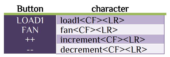
In the forever loop the controlling function of GPIO pin as-
if(strstr(RX_ST,"load1"))
    {
      HAL_GPIO_TogglePin(GPIOA,GPIO_PIN_1);
      if(HAL_GPIO_ReadPin(GPIOA,GPIO_PIN_1))
      OLCD_write_string(5,1,"LOAD 1 ON      ");
      else OLCD_write_string(5,1,"LOAD 1 OFF     ");
	  count=0;
      memset (RX_ST, '\0', 140);     // clear the buffer
	  memset (display, '\0', 140);     // clear the buffer
    }
This is the same as Bluetooth tutorial. Here we use OLED 128*64 as display purpose. For controlling fan will be same-
char fan_display[16];
uint8_t b_fan,duty=50;
if(strstr(RX_ST,"fan"))
    {
      b_fan=b_fan^0x01;
      if(b_fan)
      {
        HAL_TIM_PWM_Start(&htim15,TIM_CHANNEL_1);
        sprintf(fan_display,"FAN Sp:%i    ",duty);
        OLCD_write_string(6,1,fan_display);
      }else{
        HAL_TIM_PWM_Stop(&htim15,TIM_CHANNEL_1);
        OLCD_write_string(6,1,"FAN OFF        ");
      }
	  count=0;
      memset (RX_ST, '\0', 140);     // clear the buffer
	  memset (display, '\0', 140);     // clear the buffer
    }
For changing duty cycle, the code will be-
if(strstr(RX_ST,"increment"))
    {
     int speed=2;
      if(b_fan)
      {
       speed++;
       if(speed>=5)speed=4;
       switch(speed)
       {
       case 0: TIM15->CCR1=4999; //for 25% duty cycle
       OLCD_write_string(6,1,"FAN ON SP:25% ");
       duty=25;
       break;
       case 1: TIM15->CCR1=9999; //for 50% duty cycle
       OLCD_write_string(6,1,"FAN ON SP:50% ");
       duty=50;
       break;
       case 2: TIM15->CCR1=14999;//for 75% duty cycle
       OLCD_write_string(6,1,"FAN ON SP:75% ");
       duty=75;
       break;
       case 3: TIM15->CCR1=17999;//for 90% duty cycle
       OLCD_write_string(6,1,"FAN ON SP:90%  ");
       duty=90;
       break;
			 case 4: TIM15->CCR1=19998;//for 100% duty cycle
       OLCD_write_string(6,1,"FAN ON SP:100%  ");
       duty=100;
       break;
       }
      }
	  count=0;
      memset (RX_ST, '\0', 140);     // clear the buffer
	  memset (display, '\0', 140);     // clear the buffer
    }
if(strstr(RX_ST,"decrement"))
    {
     int speed=2;
      if(b_fan)
      {
       speed--;
       if(speed<=0)speed=0;
       switch(speed)
       {
       case 0: TIM15->CCR1=4999; //for 25% duty cycle
       OLCD_write_string(6,1,"FAN ON SP:25% ");
       duty=25;
       break;
       case 1: TIM15->CCR1=9999; //for 50% duty cycle
       OLCD_write_string(6,1,"FAN ON SP:50% ");
       duty=50;
       break;
       case 2: TIM15->CCR1=14999;//for 75% duty cycle
       OLCD_write_string(6,1,"FAN ON SP:75% ");
       duty=75;
       break;
       case 3: TIM15->CCR1=17999;//for 90% duty cycle
       OLCD_write_string(6,1,"FAN ON SP:90% ");
       duty=90;
       break;
	   case 4: TIM15->CCR1=19998;//for 100% duty cycle
       OLCD_write_string(6,1,"FAN ON SP:100%  ");
       duty=100;
       break;
       }
      }
	  count=0;
      memset (RX_ST, '\0', 140);     // clear the buffer
	  memset (display, '\0', 140);     // clear the buffer
		}
Combine all the function will be our full program. This tutorial is very lengthy & I discuss about some basic part. Please read my other articles then it will be easier to you. Please see my Youtube video & download the full code, it will help you.


 IoTthingHuB


 Visit Today : 58
 Total Visit : 41174