
In our previous article we use ESP8266 working as Station mode. In Station mode we need a wireless router for connecting ESP8266 module. In this article we use SoftAP mode of ESP8266. In Access Mode the ESP8266 works as 2.4GHz wireless router and maximum 4 devices can connect with this router.
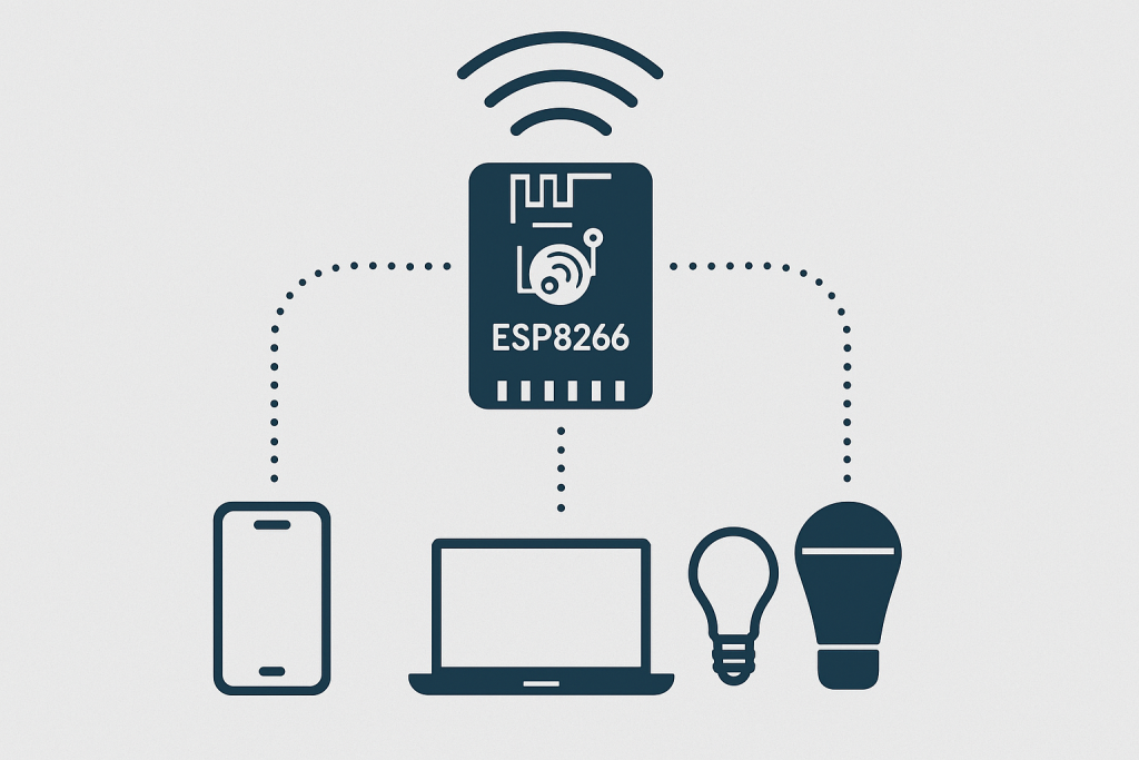
Before starting please go through my previous article for some basic knowledge of ESP8266 module. Before starting let’s see some command mode that we need in this article.
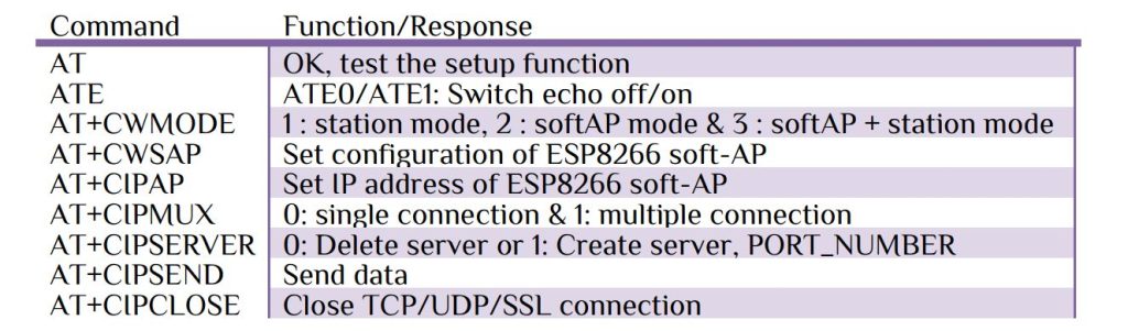
Let’s see the command parameters & there use. Simple AT command return OK string with carriage return & new line. If we send ATE0 it will stop echo otherwise echo come. Command AT+CWMODE define the mode of operations. In this article we use ESP8266 as a router HUB or access point of a network we define AT+CWMODE=2. After define the mode of operation it is time to give some name of your WiFi network provided with a password and IP address for accessing that network.
CMD> AT+CWSAP = “SSID”, “Password”, channel ID, encryption, Devices, SSID hidden
Provide any name, password & channel ID you want. ESP8266 use different types of Wi-Fi security protocols that use Pre-Shared Keys (PSK) for authentication.
1. WPA-PSK (Wi-Fi Protected Access – Pre-Shared Key)
– Uses TKIP (Temporal Key Integrity Protocol) for encryption.
– More secure than WEP, but still vulnerable to attacks.
– Older and considered less secure compared to WPA2.
2. WPA2-PSK (Wi-Fi Protected Access 2 – Pre-Shared Key)
– Uses AES (Advanced Encryption Standard) for encryption, which is much stronger than TKIP.
– More secure than WPA-PSK.
– Standard for most modern Wi-Fi networks.
3. WPA/WPA2-PSK (Mixed Mode)
– Supports both WPA-PSK (TKIP) and WPA2-PSK (AES).
– Allows older devices that only support WPA to connect while still allowing newer devices to use WPA2.
– Less secure than forcing WPA2-only, as attackers could exploit WPA vulnerabilities.
Chose any protocol level, here I chose WPA/WPA2-PSK (Mixed Mode). The other 2 parameters has there default values, so no need for assignation or change. For example to set a WiFi Router with name: “IoTtgingHuB”, password “12345678” with channel ID 5 and security level 4 as follow-
AT+CWSAP=”IoTtgingHuB”,”12345678″,5,4\r\n
CMD> AT+CIPAP= “IP”, “GateWay”, “SubNetmask”
The default APIP is 192.168.4.1, but it can be changed. ESP8266 only support class C IP address. A Class C IP address is a part of the IPv4 address classification system that was originally used to define network sizes. Address Range: 192.0.0.0 to 223.255.255.255 with Default Subnet Mask 255.255.255.0. Let’s use IP: 192.168.10.7, Gateway IP: 192.168.10.7 & Sub Netmask: 255.255.255.0 as-
AT+CIPAP=”192.168.10.7″,”192.168.10.7″,”255.255.255.0″\r\n
After configuring the IP & gateway create a server with multiple connections with server port 80.
AT+CIPMUX=1\r\n & AT+CIPSERVER=1,80\r\n
Let’s create a code for setup function. Here I use UART1 with external interrupt function. Please go through my previous article for more details.
char WIFI_NAME[] ="IoTtgingHuB";                      // Create a WiFi Name
char WIFI_PASS[] ="12345678";                         // Create a WiFi Password
char WIFI_AP_IP[]="192.168.10.7";                     // Create a WiFi AccessPoint
char display[1023],wifi_send[1023],RX_ST[1023];
ESP8266_TX("AT\r\n","OK",4000);                       // Device Checking
ESP8266_TX("ATE0\r\n","OK",4000);                     // ECHO OFF
ESP8266_TX("AT+CWMODE=2\r\n","OK",4000);              // SoftAP Mode
sprintf(wifi_send,"AT+CWSAP=\"%s\",\"%s\",5,4\r\n",WIFI_NAME,WIFI_PASS);
ESP8266_TX(wifi_send,"OK",8000);                      // Create AccessPoint Server
sprintf(wifi_send,"AT+CIPAP=\"%s\",\"%s\",\"255.255.255.0\"\r\n",WIFI_AP_IP,WIFI_AP_IP);
ESP8266_TX(wifi_send,"OK",8000);                      // Create AccessPoint IP
ESP8266_TX("AT+CIPMUX=1\r\n","OK",4000);              // Create Multiconnection
ESP8266_TX("AT+CIPSERVER=1,80\r\n","OK",4000);        // Create Server Port 80
void ESP8266_TX(char *b_send,char *return_string,uint16_t delay_time)
{
            char ESP8266_TX[10];
	sprintf(ESP8266_TX,"%s",return_string);
            sprintf(wifi_send,"%s",b_send);
	HAL_UART_Transmit(&huart1,(uint8_t*)wifi_send,strlen(wifi_send),1000);
	while(1)
	{
		sprintf(RX_ST,"%s",display);
		if(strstr(RX_ST,ESP8266_TX)) break;
	}
	HAL_Delay(delay_time);
	memset (display, '\0',1023);                       // clear the buffer
	memset (wifi_send,'\0',1023);                      // clear the buffer
	memset (RX_ST, '\0',1023);                         // clear the buffer
	count=0;
}
The interrupt callback function as follow-
uint8_t rx_char;
uint16_t count;
extern UART_HandleTypeDef huart1;
//-------------- Rx Callback Function -----
void HAL_UART_RxCpltCallback(UART_HandleTypeDef *huart)
{
  if(huart->Instance==USART1 )
  {
    display[count++]=rx_char;
    HAL_UART_Receive_IT(&huart1,&rx_char,1);
  }
}
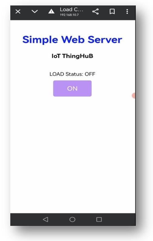
Now it is time to send data to the Access Network through IP: 192.168.10.7:80. After connecting a device either PC or Mobile through WiFi password, open any browser terminal and type 192.168.10.7. When we enter the IP address into the browser, it will return a link ID for interface with full of the browser information. After gating the link ID our next command is to send data to the browser.
CMD> AT+CIPSEND=”link ID”, “length of the string”
If you want only a single device can connect at a time by default the link ID is 0 no need to input, but in multi-connection mode any 4 device can connect at a time & link ID 0~4. After getting link ID send the string length, the ESP8266 can support maximum 2048 bytes of data. We send a total webpage data in HTML format and according to the browser response just simply turn on/off the load.
HTML code: Off condition
<!DOCTYPE html> <html>
<head><meta name=\"viewport\" content=\"width=device-width, initial-scale=1.0, user-scalable=no\">
<title>Load Control</title>
<style>html { font-family: ZCOOL XiaoWei; display: inline-block; margin: 2px auto; text-align: center;}body{margin-top: 40px;}
h1 {color: #0e18f3;margin: 45px auto 25px;}
h3 {color: #050505;margin-bottom: 40px;}
.button {display: block;width: 60px;background-color: #b589f0;border: none;color: white;padding: 15px 25px;text-decoration: none;font-size: 20px;margin: 0px auto 30px;cursor: pointer;border-radius: 5px;}
.button-on {background-color: #b589f0;}
.button-on:active {background-color: #2fd4e0;}
.button-off {background-color: #65537a;}
.button-off:active {background-color: #2fd4e0;}
 p {font-size: 16px;color:#040404;margin-bottom: 12px;}
</style></head><body><h1>Simple Web Server</h1>
<h3> IoT ThingHuB </h3>
<p>LOAD Status: OFF</p>
<a class=\"button button-on\" href=\"/loadon\">ON</a>
</body>
</html>
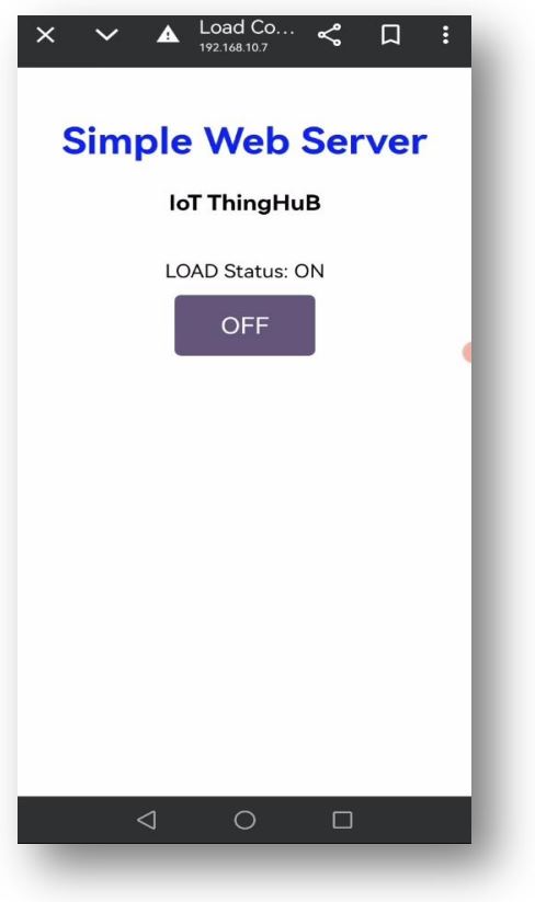
HTML code: On condition
<!DOCTYPE html> <html>
<head><meta name=\"viewport\" content=\"width=device-width, initial-scale=1.0, user-scalable=no\">
<title>Load Control</title>
<style>html { font-family: ZCOOL XiaoWei; display: inline-block; margin: 2px auto; text-align: center;}body{margin-top: 40px;}
h1 {color: #0e18f3;margin: 45px auto 25px;}
h3 {color: #050505;margin-bottom: 40px;}
.button {display: block;width: 60px;background-color: #b589f0;border: none;color: white;padding: 15px 25px;text-decoration: none;font-size: 20px;margin: 0px auto 30px;cursor: pointer;border-radius: 5px;}
.button-on {background-color: #b589f0;}
.button-on:active {background-color: #2fd4e0;}
.button-off {background-color: #65537a;}
.button-off:active {background-color: #2fd4e0;}
 p {font-size: 16px;color:#040404;margin-bottom: 12px;}
</style></head><body><h1>Simple Web Server</h1>
<h3> IoT ThingHuB </h3>
<p>LOAD Status: ON</p>
<a class=\"button button-off\" href=\"/loadoff\">OFF</a>
</body>
</html>
Assume the link id is 0 & in on condition the total html character is 942 bytes. The command –
AT+CIPSEND=0,941\r\n
Wrap return “>” after execute command. Send the full html code & terminate with AT+CIPCLOSE =” link ID”. Please wait at least 1 second before sending next AT command. Interesting that if we send AT+CIPCLOSE =5 all connections will be closed. Here I describe the basic structure & full steps one by one. It is not best practice to use STM32 as core & ESP8266 as slave, because the ESP8266 can properly handle all the command & a development board for lots of more function. We will do all the staff with only a single ESP8266 module in some other article. For device setting & how it works please see my YouTube video, keep learning.


 IoTthingHuB


 Visit Today : 58
 Total Visit : 41174